Systems and methods for flaw detection and monitoring at elevated temperatures with wireless communication using surface embedded, monolithically integrated, thin-film, magnetically actuated sensors, and methods for fabricating the sensors

a technology of wireless communication and flaw detection, applied in the direction of magnetic body analysis, solids analysis using sonic/ultrasonic/infrasonic waves, magnetic resonance analysis, etc., can solve the problem of limited access to such systems, presently no operational sensors for direct measurement of material damage (cracking), and relatively easy ae measurements. problem, to achieve the effect of effective structural health management and prognosis

Active Publication Date: 2013-07-16
SOUTHWEST RES INST
View PDF34 Cites 6 Cited by
  • Summary
  • Abstract
  • Description
  • Claims
  • Application Information

AI Technical Summary

Benefits of technology

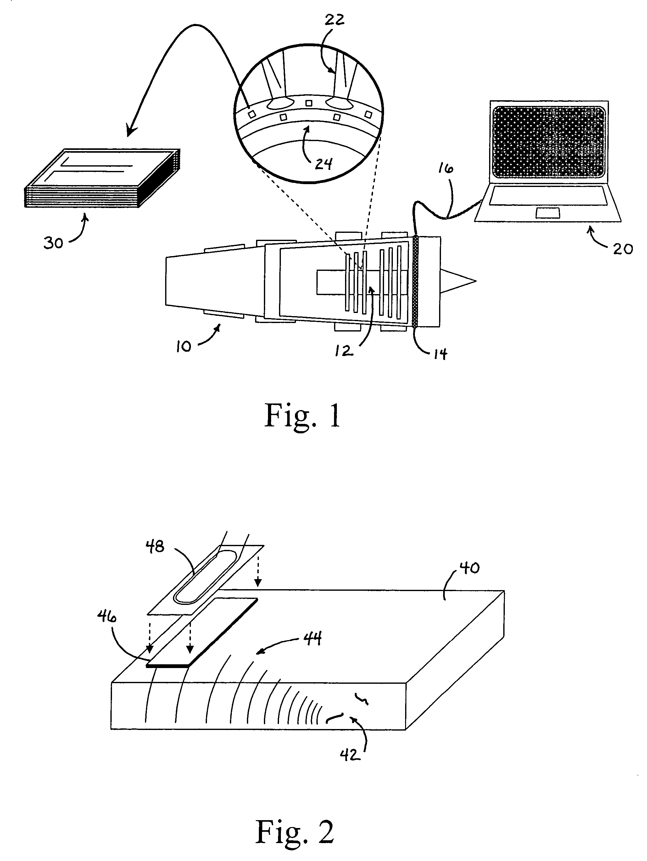
[0013]One embodiment (that forms the basis of the present invention) for using embedded sensors in association with a system for monitoring a turbine engine disc is illustrated in FIG. 1. The system as generally shown includes a plurality of sensors 30 (as described in greater detail below) that are placed (for example) near fracture critical components such as turbine blades 22 and turbine discs 24. These sensors 30 positioned on the moving components 12 of turbine engine 10 are in wireless RF signal connection to a receiving antenna 14 positioned on a stationary component of engine 10. Antenna 14 is connected through a signal line 16 to data processing instrumentation 20 for signal analysis. This concept includes distributed thin-film magnetostrictive sensors that are integrated onto the component surface near fracture critical locations (FCLs). Periodically activating the thin-film sensors by generating ultrasonic waves enables interrogation of the material component for defects through the detection of reflected waves from the defect using the “pulse-echo” mode of detection. The complete sensor system concept also includes a fully integrated antenna for the harvesting of energy using microwaves (or other frequency electromagnetic waves) thereby providing power for sensor activation and radio frequency (RF) communication of the backscattered ultrasonic signals. This fully integrated, monolithic, wireless, self-powered crack detection sensor provides effective structural health management and prognosis in turbine engines, as well as other high-value assets.
[0014]A thin-film sensor form factor offers unique advantages over other detector architectures in terms of performance and integration simplicity (a relatively simple architecture for monolithic surface integration), mass-production compatibility to micro-system manufacturing processes, and durability under the severe challenges posed by high-temperature operating environments. In theory, several thin-film materials and associated physical phenomenon are possible including magnetostrictive (Ms), piezoelectric, or shape memory, all of which can be deposited as thin films. However, magnetostrictive thin films are seen as providing one of the best modes for structuring a sensor for use in the system of the present invention since they offer several attractive features: a) a high energy output for remote-control actuation and communication, b) a wide range of candidate material systems (and associated process flexibility to meet end-use requirements), and c) inherent durability and robustness.
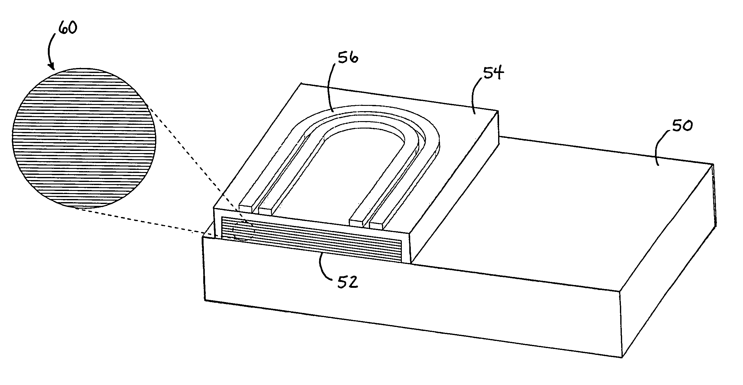
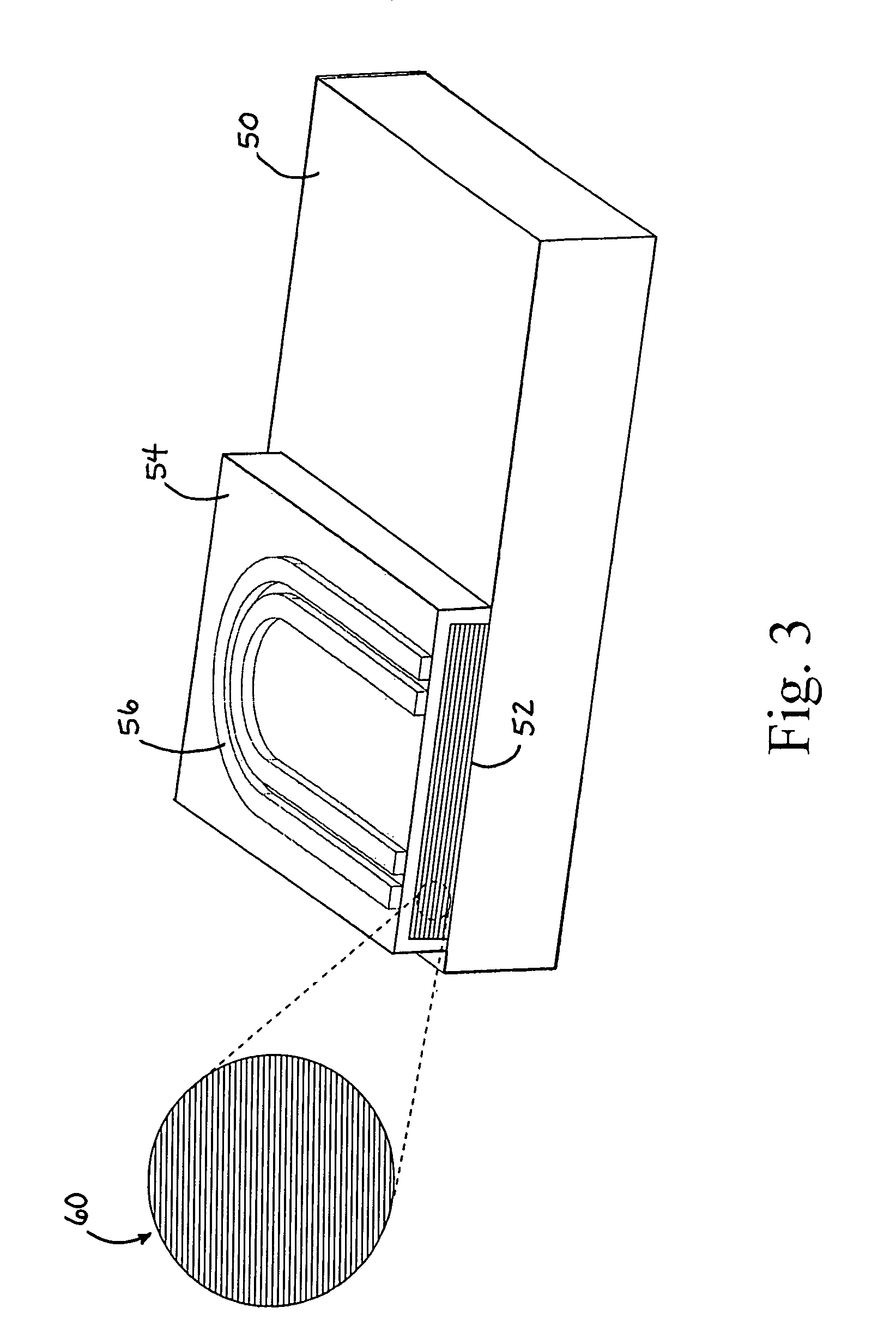
[0017]The method for manufacturing the engineered, monolithically integrated, multi-layered (nano-composite), thin-film structure includes a number of customizing factors including the magnetron sputtering (or vapor deposition) of alternating layers of a high (hard) magnetostrictive material (iron / rare earth or similar alloy) and a high magnetization (soft) material (FeCo or similar) directly onto sensing platform or onto a flexible backing substrate that can later be affixed to sensing platform. Composite magnetostrictive layer properties, such as magnetostriction coefficient, saturation magnetization, and Curie temperature (thermal stability), can be engineered by adjusting layer thicknesses (2 nm-50 nm), soft / hard layer ratio (typically greater than 1) and sputtering deposition parameters (with and without ion assist and / or RF sample bias) with minimum total layered composite thickness such that losses due to skin depth effects are minimized (typically greater than 3 microns). Composite magnetostrictive layers can also be post-annealed in a magnetic bias field or annealed in-situ as part of elevated temperature service to enhance performance.
[0021]A further important aspect of the manufacturing process may include steps in which the magnetic spin orientation is engineered, thereby eliminating the need for magnetic biasing with permanent magnets prior to activation, or during operation. The manufacturing method may also include steps in which the dielectric layer and activation layer are deposited by methods other than magnetron sputtering, such as other PVD, wet chemical, or plasma / flame spray techniques. Other types of magnetostrictive materials (other than iron-based) may also be substituted to achieve specific properties or enhance actuation performance.

Problems solved by technology

However, obtaining such a measurement presents numerous technical challenges arising from the thermal and stress environments, combined with the high rotational speed and limited accessibility of such systems.
Consequently, it is not surprising that there are presently no operational sensors for direct measurement of material damage (cracking) during component operation.
Although vibration and AE measurements are relatively easy to make, analyzing the results in order to extract the cracking signature from the overall rotor dynamics, or the acoustic background, continues to be a significant challenge.
However, these techniques require component disassembly and a relatively well controlled environment; consequently they are not adaptable to on-line sensing in the operating environment.
However, considerable uncertainty exists in the usage and sensor inputs, as well as the required modeling and associated materials property inputs.
However, the disadvantage of these tools is that they rarely involve consideration of the underlying physical processes.
Consequently, they require considerable empirical calibration or “training” for each specific application of interest.
In contrast, inspections performed continually (i.e. once every flight) result in markedly lower probability of failure even with relatively coarse inspection sensitivities of 200 to 300 mils (in size).

Method used


Image

  • Systems and methods for flaw detection and monitoring at elevated temperatures with wireless communication using surface embedded, monolithically integrated, thin-film, magnetically actuated sensors, and methods for fabricating the sensors
  • Systems and methods for flaw detection and monitoring at elevated temperatures with wireless communication using surface embedded, monolithically integrated, thin-film, magnetically actuated sensors, and methods for fabricating the sensors
  • Systems and methods for flaw detection and monitoring at elevated temperatures with wireless communication using surface embedded, monolithically integrated, thin-film, magnetically actuated sensors, and methods for fabricating the sensors

Examples


Embodiment Construction

Probabilistic Analysis of Prognosis Uncertainty (Preliminary Discussion)

[0042]Probabilistic analyses (detailed in the above referenced Provisional Patent Application, the disclosure of which has been incorporated herein by reference) suggests that continual monitoring of with sensors that are 6 to 10 times less sensitive than those presently used in depot inspections (about 30 mils) can achieve high component reliability (low probabilities of failure). This benefit results from the continual feedback that enables damaged components to be identified and removed from service throughout their life. Although this concept of trading-off interrogation sensitivity for frequency of interrogation is believed to be generally true, the specific minimum sensitivities required for effective onboard sensing will depend on the critical crack size associated with the specific fatigue critical location. That is, for the specific case of a bolt-hole in a generic disc, for example, the critical crack ...


PUM

PropertyMeasurementUnit
thicknessaaaaaaaaaa
thicknessaaaaaaaaaa
sizeaaaaaaaaaa

Abstract

Systems and methods for flaw detection and monitoring at elevated temperatures with wireless communication using surface embedded, monolithically integrated, thin-film, magnetically actuated sensors, and methods for fabricating the sensors. The sensor is a monolithically integrated, multi-layered (nano-composite), thin-film sensor structure that incorporates a thin-film, multi-layer magnetostrictive element, a thin-film electrically insulating or dielectric layer, and a thin-film activating layer such as a planar coil. The method for manufacturing the multi-layered, thin-film sensor structure as described above, utilizes a variety of factors that allow for optimization of sensor characteristics for application to specific structures and in specific environments. The system and method integrating the multi-layered, thin-film sensor structure as described above, further utilizes wireless connectivity to the sensor to allow the sensor to be mounted on moving components within the monitored assembly.

Description

CROSS REFERENCE TO RELATED APPLICATIONS[0001]This application claims the benefit under Title 35 United States Code §119(e) of U.S. Provisional Application No. 60 / 721,922 filed Sep. 28, 2005, the full disclosure of which is incorporated herein by reference.BACKGROUND OF THE INVENTION[0002]1. Field of the Invention[0003]The present invention relates generally to systems and methods for flaw detection in physical structures, especially high value asset structures. The present invention relates more specifically to systems and methods for flaw detection and monitoring at elevated temperatures with wireless communication using surface embedded, monolithically integrated, thin-film, magnetically actuated sensors, and additionally to methods for fabricating sensors used in such systems.[0004]2. Description of the Related Art[0005]High quality, robust sensors capable of on-board detection and monitoring of damage would result in significant enhancements to the safety, reliability, and avail...

Claims


Application Information

Patent Timeline
Patent Type & Authority Patents(United States)
IPC IPC(8): G01N29/04G01R33/18H01L41/06
CPCB82Y25/00C23C14/165C23C14/3492C23C14/5806G01N27/82H01F10/3222H01L41/06H01F10/3295H01F41/18Y10T428/32H01F10/3286H01F10/136H10N35/80
Inventor LANNING, BRUCE R.LIGHT, GLENN M.HUDAK, JR., STEPHEN J.MORYL, JAMES A.
Owner SOUTHWEST RES INST
Why Eureka
Try Eureka