
Semiconductor laser driving device and image forming apparatus having the same

a driving device and semiconductor technology, applied in semiconductor lasers, electrical devices, laser details, etc., can solve the problem that the deteriorated semiconductor laser ld may not be replaced almost immediately, and achieve the effect of accurate detection of the deterioration of the semiconductor laser and small circuit siz

Inactive Publication Date: 2013-07-09
RICOH KK
View PDF28 Cites 2 Cited by
  • Summary
  • Abstract
  • Description
  • Claims
  • Application Information

AI Technical Summary

Benefits of technology

The present invention is a semiconductor laser driving device and image forming apparatus that can detect the deterioration of the semiconductor laser based on the bias current setting signal and switching current setting signal, and generate a deterioration detecting signal for transmission. This configuration allows for accurate detection of semiconductor laser deterioration with minimal circuit size, regardless of the characteristics of the semiconductor laser and its usage conditions.

Problems solved by technology

As a result, the deteriorated semiconductor laser LD may not be replaced almost immediately after the semiconductor laser LD becomes unable to emit light.
Further, there may be another case where the semiconductor laser LD becomes unable to emit light during its manufacturing process.

Method used


Image

  • Semiconductor laser driving device and image forming apparatus having the same
  • Semiconductor laser driving device and image forming apparatus having the same
  • Semiconductor laser driving device and image forming apparatus having the same

Examples


first embodiment

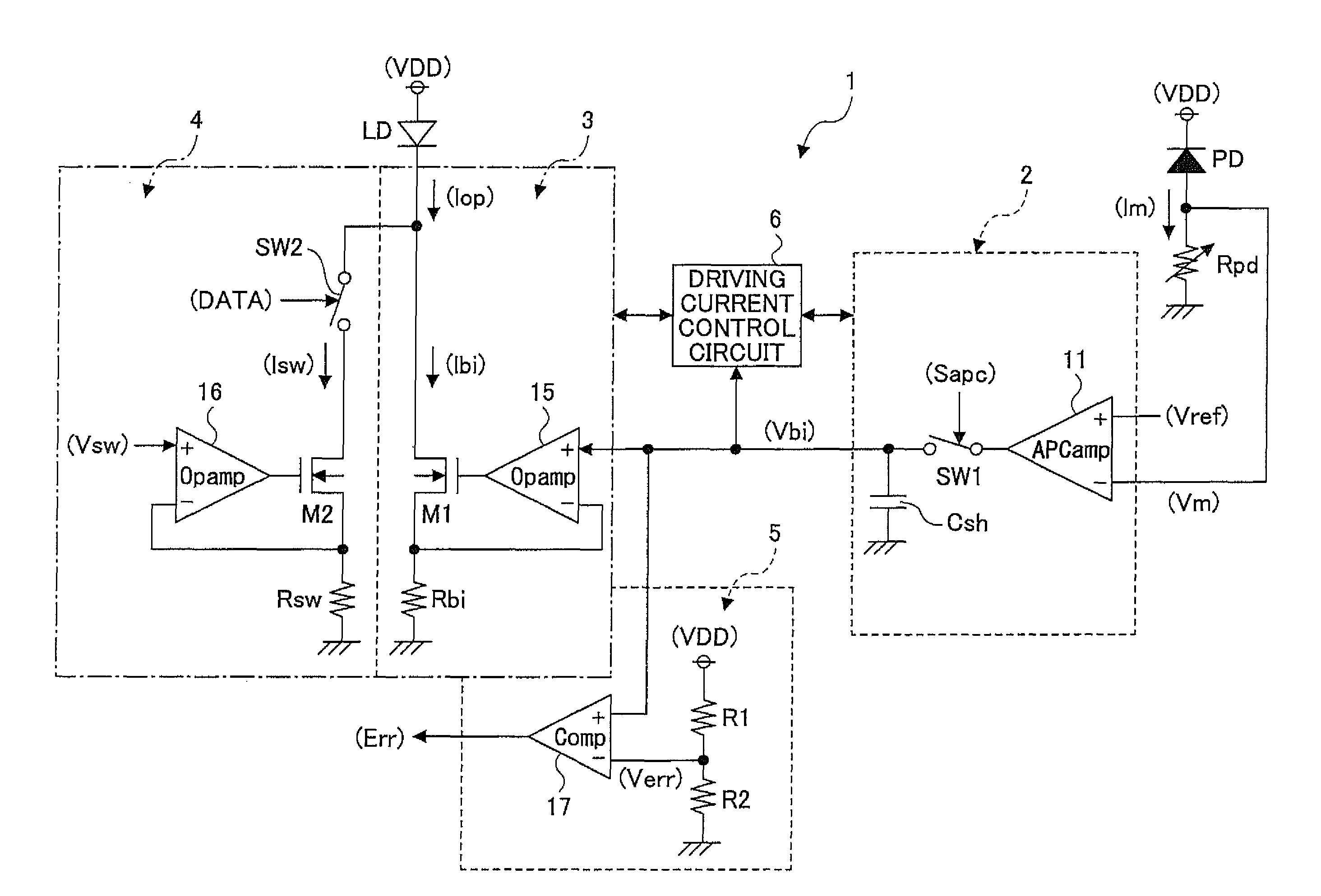
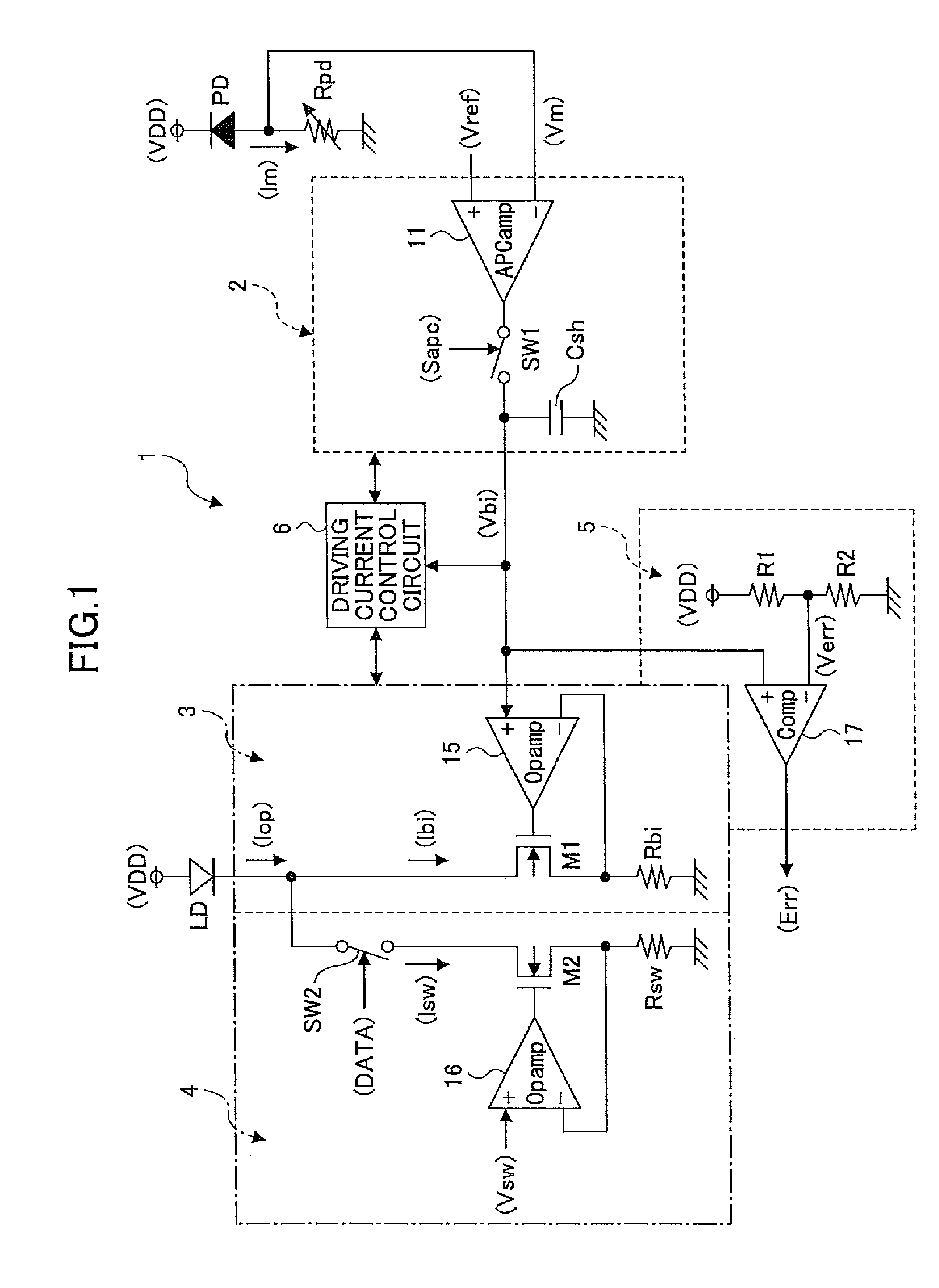
[0111]FIG. 1 is a circuit diagram showing an exemplary configuration of a semiconductor laser driving device according to a first embodiment of the present invention.

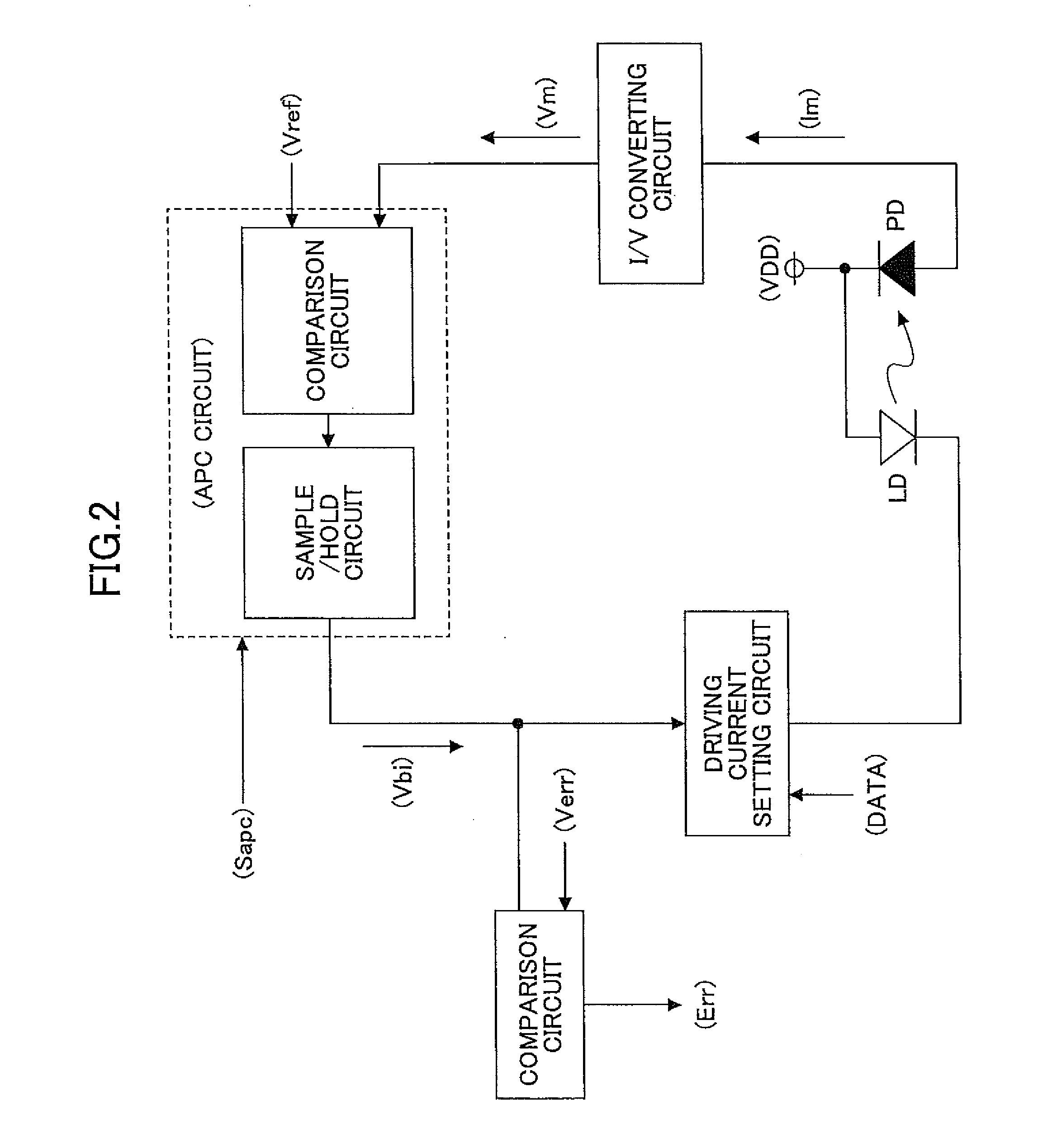
[0112]The semiconductor laser driving device 1 in FIG. 1 performs control (hereinafter referred to as the APC (Automatic Power Control)) to keep the light amount of the semiconductor laser LD constant in response to the variation of the forward current-optical output characteristics (i-L characteristics) of the semiconductor laser such as a laser diode LD, the variation being caused by, for example, temperature change or deterioration over time. In the semiconductor laser driving device 1, the emitted light amount of the semiconductor laser LD is received by a photo diode PD, and the APC is performed in response to the received light amount. The descriptions herein are made assuming that the semiconductor laser driving device 1 is being used in an image forming apparatus such as a laser printer and a digital copier.

[011...

second embodiment

[0135]In the above first embodiment, a case is described where the semiconductor laser driving device 1 is realized by analog circuits. However, digital circuits along with current-output-type D / A (digital-to-analog) converters may be used. Next, a semiconductor laser driving device 1c having digital circuits according to a second embodiment of the present invention is described.

[0136]FIG. 12 is an exemplary circuit configuration diagram of the semiconductor laser driving device 1c according to the second embodiment of the present invention. The same reference numerals in FIG. 12 denote the same or similar elements in FIG. 1. FIG. 12 shows a case where the APC is performed with respect to both the bias current Ibi and the switching current Isw.

[0137]In the semiconductor laser driving device 1c of FIG. 12, the emitted light amount of the semiconductor laser LD is received by the photo diode PD, and the APC is performed in response to the received light amount.

[0138]As shown in FIG. 1...


PUM


Abstract

A semiconductor laser driving device and an image forming apparatus are disclosed that are capable of accurately detecting the deterioration of the semiconductor laser with a smaller circuit size and regardless of the variation of the characteristics of the semiconductor laser and the use conditions of the semiconductor laser by adding a minimum circuit are disclosed. In the semiconductor laser driving device, the output voltage generated by an operational amplifier circuit by amplifying a voltage difference between a monitoring voltage (Vm) and a predetermined reference voltage (Vref) is transmitted to a bias current generating circuit unit as a bias current setting voltage (Vbi) through a sample / hold circuit having a switch (SW1) and a sample / hold capacitor (Csh). When the bias current setting voltage (Vbi) is greater than a predetermined voltage, a deterioration detecting circuit transmits a deterioration detecting signal indicating that the deterioration of the semiconductor laser is detected.

Description

TECHNICAL FIELD[0001]The present invention relates to a semiconductor laser driving device capable of controlling an emitted light amount of the semiconductor laser of the semiconductor laser driving device. More particularly, the present invention relates to a semiconductor laser driving device and an image forming apparatus having the semiconductor laser driving device further capable of detecting the deterioration of the semiconductor laser.BACKGROUND ART[0002]Conventionally, a general purpose semiconductor laser used for recording in an image forming apparatus has the so-called APC (Automatic Power Control) function to control an emitted light amount of the semiconductor laser. When the APC function is performed, the emitted light amount is periodically detected by a photo sensor disposed in the vicinity of the semiconductor laser, and a detection signal in accordance with the detected light amount is output from photo sensor to feed back to the driving circuit which drives the ...

Claims


Application Information

Patent Timeline
Patent Type & Authority Patents(United States)
IPC IPC(8): H01S3/00
CPCH01S5/0021H01S5/042H01S5/0683
Inventor KAMATANI, TOMOHIKO
Owner RICOH KK
Learn More