
Tool for implantation of replacement heart valve

a technology for implantation tools and heart valves, which is applied in the field of holders for implantation of replacement heart valves, can solve the problems of life-threatening conditions, flexible replacement heart valves, and the inability to function normally of one or more heart valves, and achieve the effect of facilitating surgical implantation procedures and simplifying surgical procedures

Active Publication Date: 2013-07-09
MEDTRONIC PS MEDICAL
View PDF34 Cites 30 Cited by
  • Summary
  • Abstract
  • Description
  • Claims
  • Application Information

AI Technical Summary

Benefits of technology

The present invention provides an implant holder that can hold a flexible implant in place during surgery without needing to manage its shape and orientation simultaneously. This makes the surgical procedure easier and faster for the surgeon.

Problems solved by technology

In some individuals, one or more heart valves may not function normally, typically as a result of disease-induced valve damage, degeneration, or a congenital defect.
Valve dysfunction can include valve regurgitation, which can be a life-threatening condition.
Mechanical prostheses are generally formed of artificial materials and rigidities which may be easily handled during surgery, but are more prone to thrombogenesis, and therefore typically require prolonged anti-coagulation therapy.
Flexible replacement heart valves, such as flexible bioprosthetic valves may be stented or unstented.
Unstented replacement valves do not include commisure support members to configurationally maintain the replacement valves during implantation, and potentially further in permanent use.
While stented valves provide a relatively stable and self-supporting structure to facilitate proper implantation and alignment of the commisures, the stent frames can result in narrowing of the valve orifice, and can also cause significant stresses on the commisures during valvular operation.
Such stresses can lead to valve degradation and dysfunction.
However, unstented valves do not have commisure support, such that implantation of the valve requires a more exacting surgical procedure to properly orient the annulus and commisures at the implantation site.
Due to the flexible structure of the bioprosthetic valves, such placement and securement is difficult.
Few devices are currently available to aid the surgeon in correctly orienting the replacement valves in the implantation procedure.
In particular, devices are not currently available for maintaining the replacement bioprosthetic valve in a correct orientation and shape while the surgeon secures such replacement valve in an appropriate coronary sinus.

Method used


Image

  • Tool for implantation of replacement heart valve
  • Tool for implantation of replacement heart valve
  • Tool for implantation of replacement heart valve

Examples


example

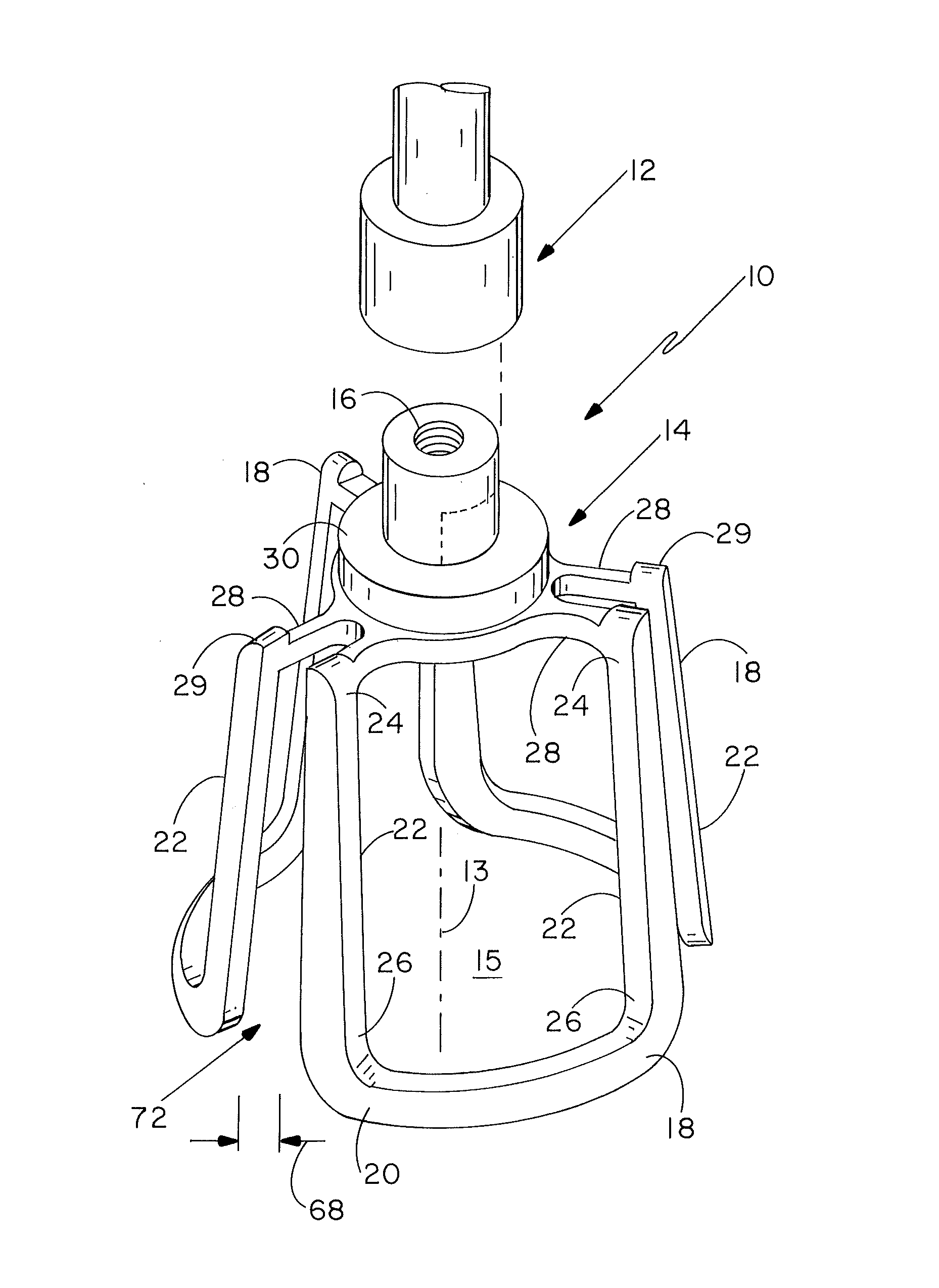
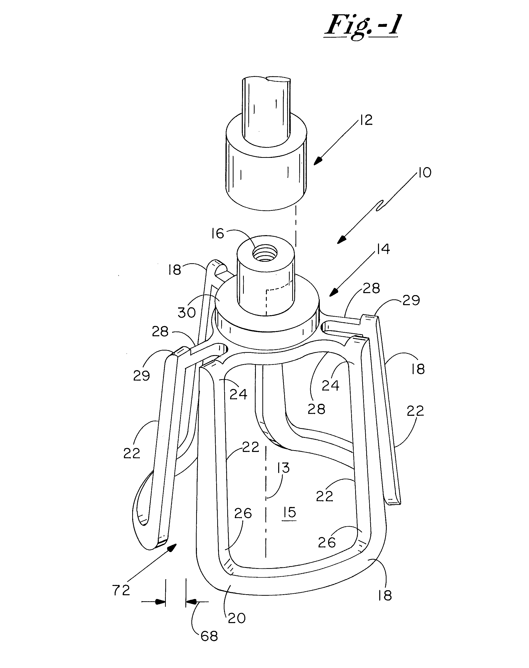
[0035]The following sets forth one example embodiment of a holder frame 14 of the present invention. It is to be understood, however, that the following dimensions are merely exemplary of a single embodiment of the present invention, and that Applicants contemplate a variety of embodiments, including various dimensions and relative dimensions of the portions of holder frame 14. Specifically, Applicants contemplate that holder frame 14 may be variously dimensioned so as to appropriately accommodate replacement valves or other implants of various sizes.

[0036]The following table sets forth example dimensions for portions of holder frame 14 described above:

[0037]

Holder Frame PortionDimensions (mm)Circumference 6481.6 (arcuate)Annulus Support Portions 2023.0 (arcuate)Commisure Support Portions 2219.5 (height)Protrusions 29 2.0 (height)Slot 72 4.2 (min. width)Hub 30 6.4 (diameter)


PUM


Abstract

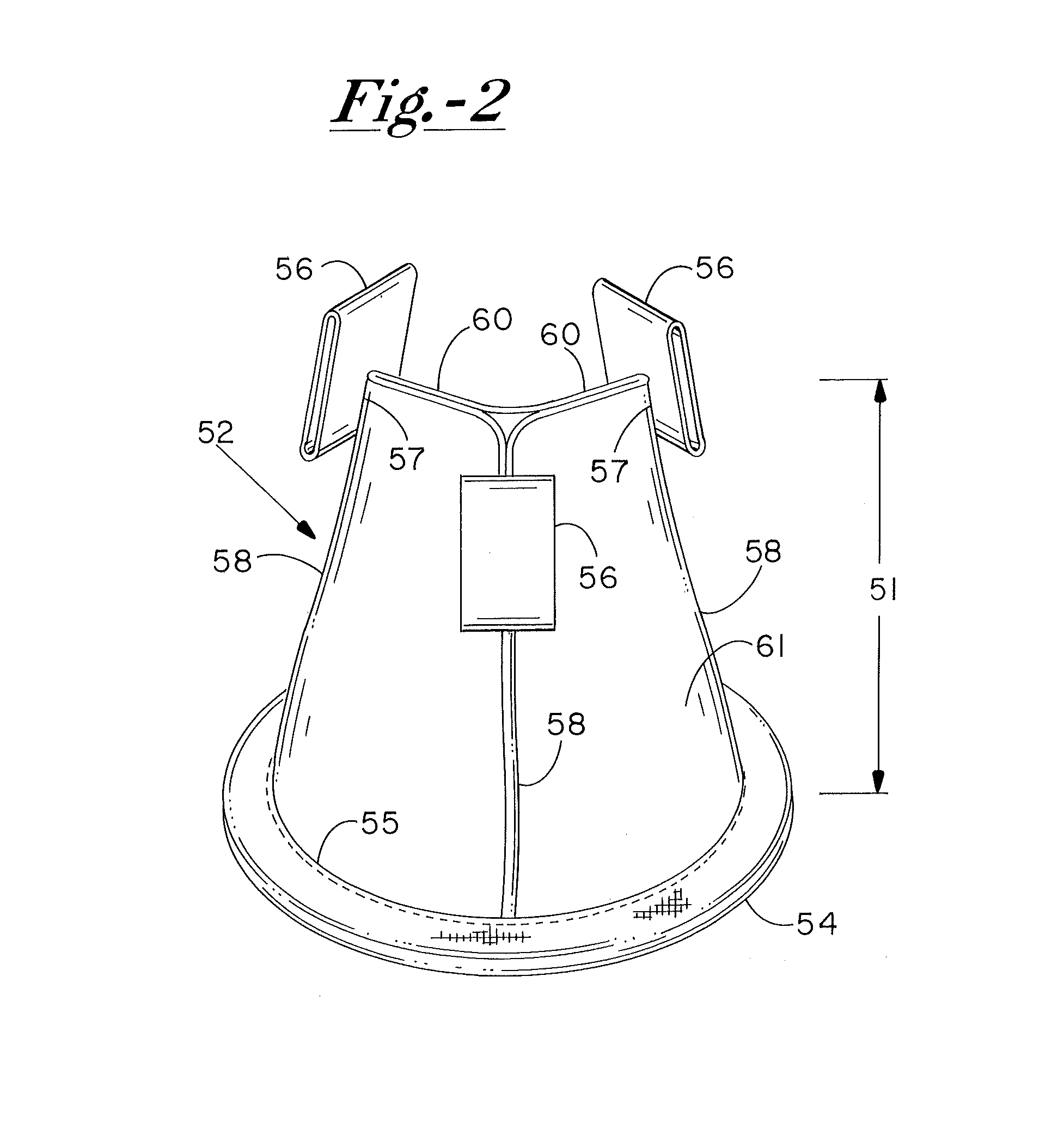
An implant holder for removably retaining an implant during an implantation procedure includes a holder device having a frame defining a chamber. The frame may be configured for removable retention of an implant, such as the flexible bioprosthetic heart valve, substantially within the chamber. The removable retention of the implant to the implant holder maintains the implant in an orientation and shape suitable for implantation.

Description

CROSS-REFERENCE TO RELATED APPLICATIONS[0001]This application claims priority to U.S. Provisional Patent Application Ser. No. 61 / 044,737, filed on Apr. 14, 2008 and entitled “Tool for Implantation of Replacement Heart Valve”, the content of which being incorporated herein in its entirety.FIELD OF THE INVENTION[0002]The present invention relates to devices for implant installation generally, and more particularly to a holder device for use in connection with implantation of replacement heart valves.BACKGROUND OF THE INVENTION[0003]In some individuals, one or more heart valves may not function normally, typically as a result of disease-induced valve damage, degeneration, or a congenital defect. Valve dysfunction can include valve regurgitation, which can be a life-threatening condition. One method for treating valve dysfunction is valve replacement with one of a variety of replacement valve types. Such replacement heart valves may be relatively rigid or may be flexible, and may be gen...

Claims


Application Information

Patent Timeline
Patent Type & Authority Patents(United States)
IPC IPC(8): A61F2/24
CPCA61F2/2427
Inventor ELIZONDO, DAVIDPETERSON, LARRYTHAI, YANGANDRZEJ, MALEWICZ M.
Owner MEDTRONIC PS MEDICAL
Learn More