
Video processing method, encoding device, decoding device, and data structure for facilitating layout of a restored image frame

a video processing and image frame technology, applied in the direction of color television with bandwidth reduction, signal generator with optical-mechanical scanning, signal system, etc., can solve the problems of unclear picture at the receiving end, no further adjustment in resolution is contemplated, and the approach is not ideal. , to achieve the effect of facilitating the layout of the restored image fram

Active Publication Date: 2013-07-02
ACER INC
View PDF7 Cites 3 Cited by
  • Summary
  • Abstract
  • Description
  • Claims
  • Application Information

AI Technical Summary

Benefits of technology

[0009]Therefore, the object of the present invention is to provide a video processing method, an encoding device, a decoding device, and a data structure for facilitating layout of a restored image frame.

Problems solved by technology

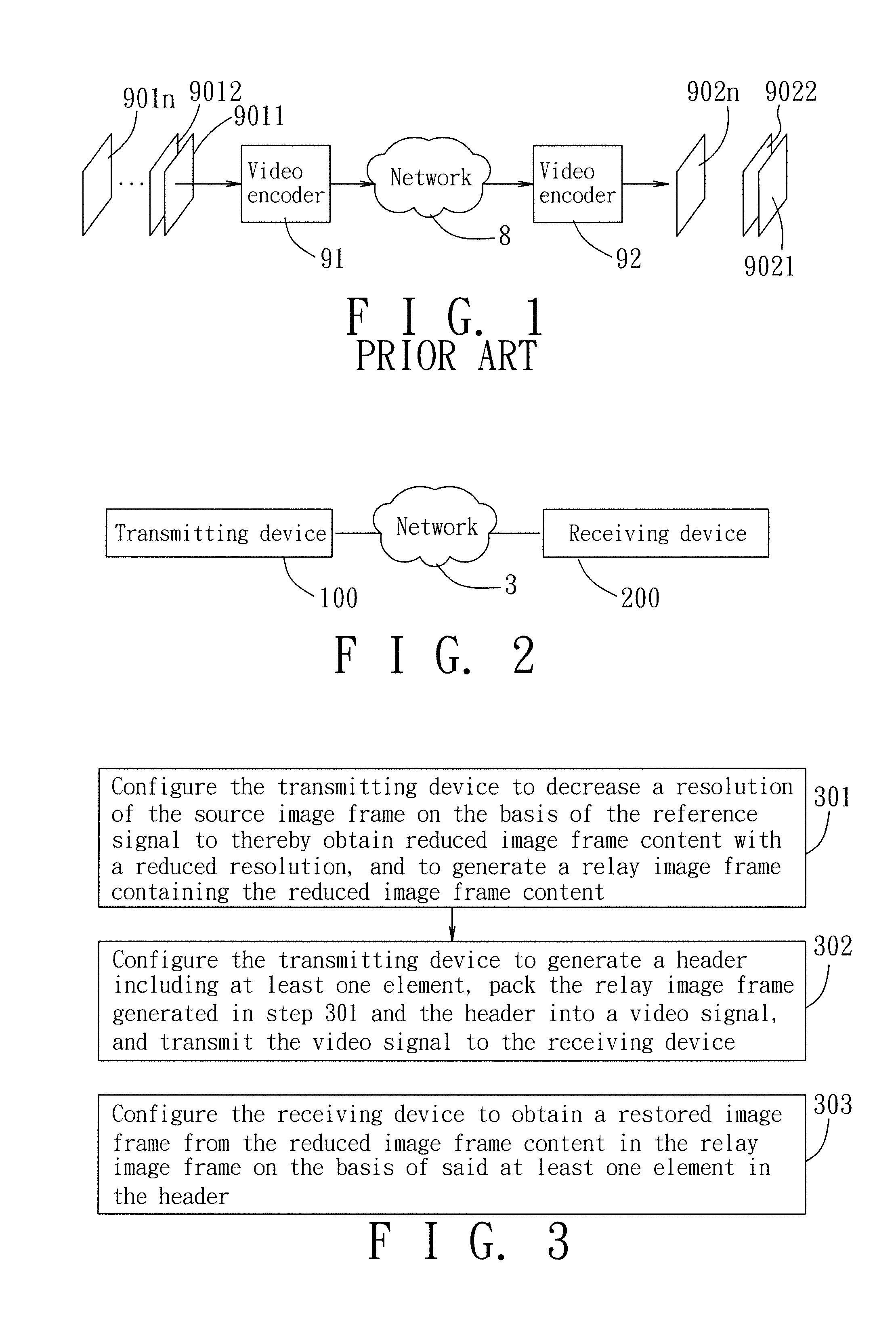
Therefore, if the bandwidth of the network 8 is abruptly reduced, and the encoding bit rate (data amount of each frame×frame rate) exceeds the bandwidth, this will result in intermittent and / or unclear pictures at the receiving end.
However, such an approach is not ideal since the resulting output image frames 9021˜902n will be of a low quality.
However, no further adjustment in resolution is contemplated when such a technique is employed.
The large number of video encoders involved in, for example, a 16- or 32-channel video monitor system (i.e., one video encoder for each channel) results in high system costs and complexity.
Moreover, a separate bit stream is transmitted over a network for each video encoder, which is burdensome on the network.
Finally, as with the conventional video conference system, the conventional video monitor system is unable to effectively cope with the problems associated with abrupt reductions in network bandwidth.

Method used


Image

  • Video processing method, encoding device, decoding device, and data structure for facilitating layout of a restored image frame
  • Video processing method, encoding device, decoding device, and data structure for facilitating layout of a restored image frame
  • Video processing method, encoding device, decoding device, and data structure for facilitating layout of a restored image frame

Examples


Embodiment Construction

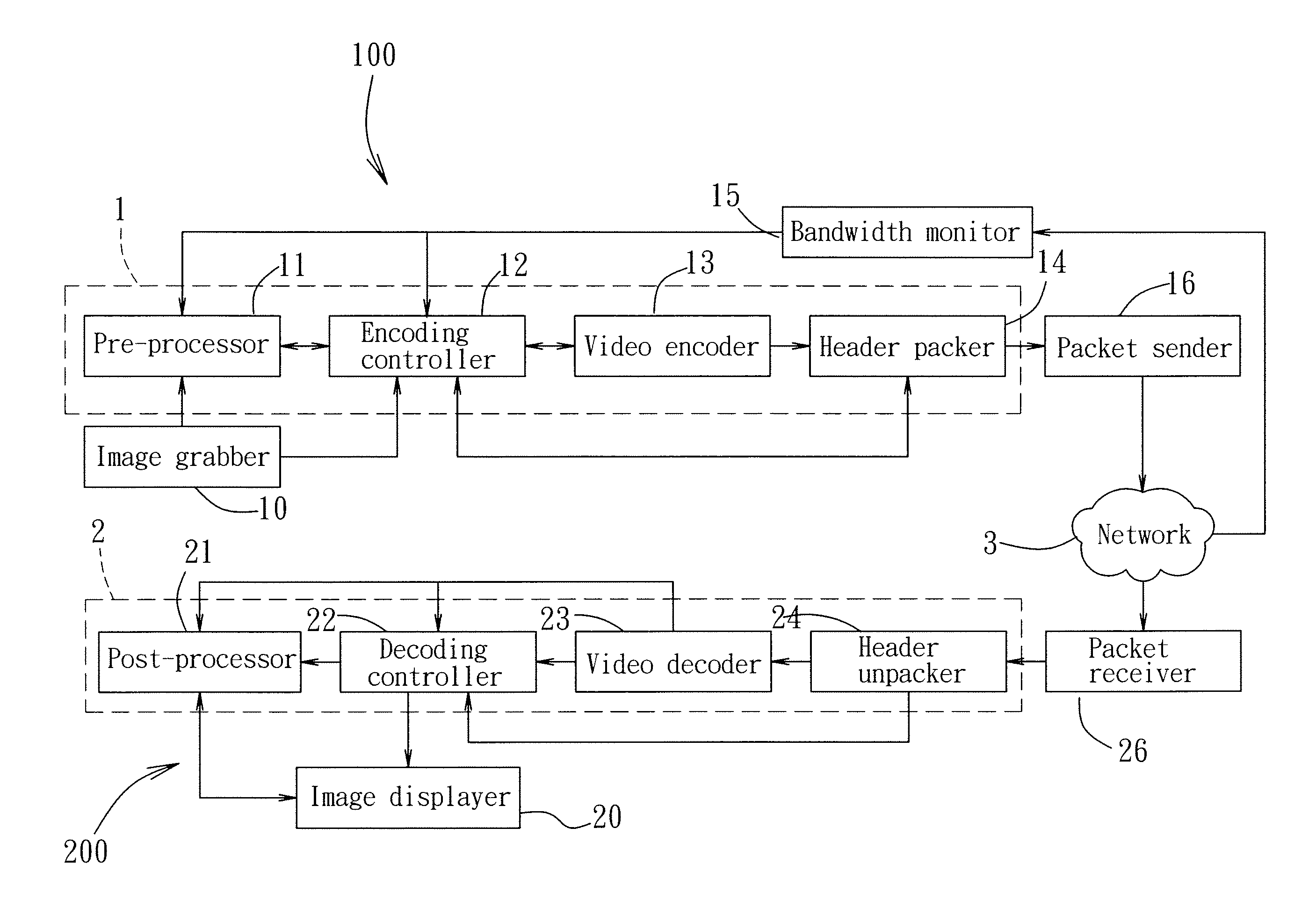
[0030]Referring to FIGS. 2 and 3, a video processing method according to a preferred embodiment of the present invention is implemented by an encoding device 100 and a decoding device 200 of a video processing system according to a preferred embodiment of the present invention. The encoding device 100 receives at least one source image frame and a reference signal, and communicates with the decoding device 200 via a network 3.

[0031]In step 301 of the video processing method, the encoding device 100 is configured to decrease a resolution of the source image frame on the basis of the reference signal to thereby obtain reduced image frame content with a reduced resolution, and to generate a relay image frame containing the reduced image frame content. In some embodiments, the reference signal is a detected bandwidth of the network 3, and in step 301, the encoding device 100 is configured to decrease the resolution of the source image frame when the bandwidth of the network 3 is less th...


PUM


Abstract

A video processing method is implemented by encoding and decoding devices. The video processing method includes: configuring the encoding device to decrease a resolution of a received at least one source image frame based on a received reference signal to obtain reduced image frame content with a reduced resolution, and to generate a relay image frame containing the reduced image frame content; configuring the encoding device to generate a header including at least one element containing information of the reduced image frame content, pack the relay image frame and the header into a video signal, and transmit the video signal to the decoding device; and configuring the decoding device to obtain a restored image frame from the reduced image frame content based on the element in the header. A data structure, and encoding and decoding devices are also disclosed.

Description

CROSS-REFERENCE TO RELATED APPLICATION[0001]This application claims priority of Taiwanese Application No. 097150441, filed on Dec. 24, 2008.BACKGROUND OF THE INVENTION[0002]1. Field of the Invention[0003]The present invention relates to a video processing method, an encoding device, a decoding device, and a data structure for facilitating layout of a restored image frame.[0004]2. Description of the Related Art[0005]A conventional videoconference system, such as that shown in FIG. 1, is an example of a video processing system. A plurality of source image frames 9011˜901n included in a real-time image sequence are compressed into video signals by a video encoder 91. The video signals are then transmitted via a network 8 to a video decoder 92. The video decoder 92 decodes the video signals for recovery into a series of output image frames 9021˜902n. [0006]In the conventional videoconference system, the entire process from inputting the source image frames 9011˜901n into the video encod...

Claims


Application Information

Patent Timeline
Patent Type & Authority Patents(United States)
IPC IPC(8): H04N7/12H04N11/04H04N11/02H04N19/89
CPCH04N19/176H04N19/70H04N19/172H04N19/46H04N19/59H04N19/14H04N19/184H04N19/85H04N19/132
Inventor PENG, HSIN-YUANCHIANG, CHI-CHENG
Owner ACER INC
Learn More