
Multi-layer substrate

a substrate and multi-layer technology, applied in the field of multi-layer substrates, can solve the problems of reducing the transformation from a differential mode to a common mode, excite a large reflection loss, and other unwanted effects, and achieve the effect of reducing the transformation

Active Publication Date: 2013-07-02
NEC CORP
View PDF19 Cites 6 Cited by
  • Summary
  • Abstract
  • Description
  • Claims
  • Application Information

AI Technical Summary

Benefits of technology

The present invention aims to reduce interference between different signals in electronic circuits. This is achieved by improving the structure of the ground system and using dummy pads in the transition area between signal vias and ground vias. This results in a more efficient and reliable electronic circuit design.

Problems solved by technology

Keeping the characteristic impedance within a predetermined level (within 10% as an example) through the whole path of an interconnection circuit between terminals is an important problem, especially in the design of the multi-layer substrate used in high-speed data transmission.
This problem is equally related to both single-ended and differential signaling.
Also, reduction of transformation from a differential mode to a common mode and from the common mode to the differential mode is another issue which has to be overcome in the high-speed multi-layer substrate.
As result, a transition from a via structure (single-ended or differential structure) to a planar transmission line becomes at the front because in this transition characteristic impedance mismatching can appear due to a large clearance hole.
This impedance mismatching can excite a large reflection loss, a stray resonance and other unwanted effects.
Moreover, in differential interconnection circuits, impedance mismatching can give a considerable increase of transformation between differential and common modes.

Method used


Image

  • Multi-layer substrate
  • Multi-layer substrate
  • Multi-layer substrate

Examples


Embodiment Construction

[0017]Hereinafter, several types of multi-layer substrate having the multi-tier transition between a signal via structure and a planar transmission line according to the present invention will be described in detail with reference to the attached drawings. Here, it would be well understood that this description should not be viewed as narrowing the appended claims.

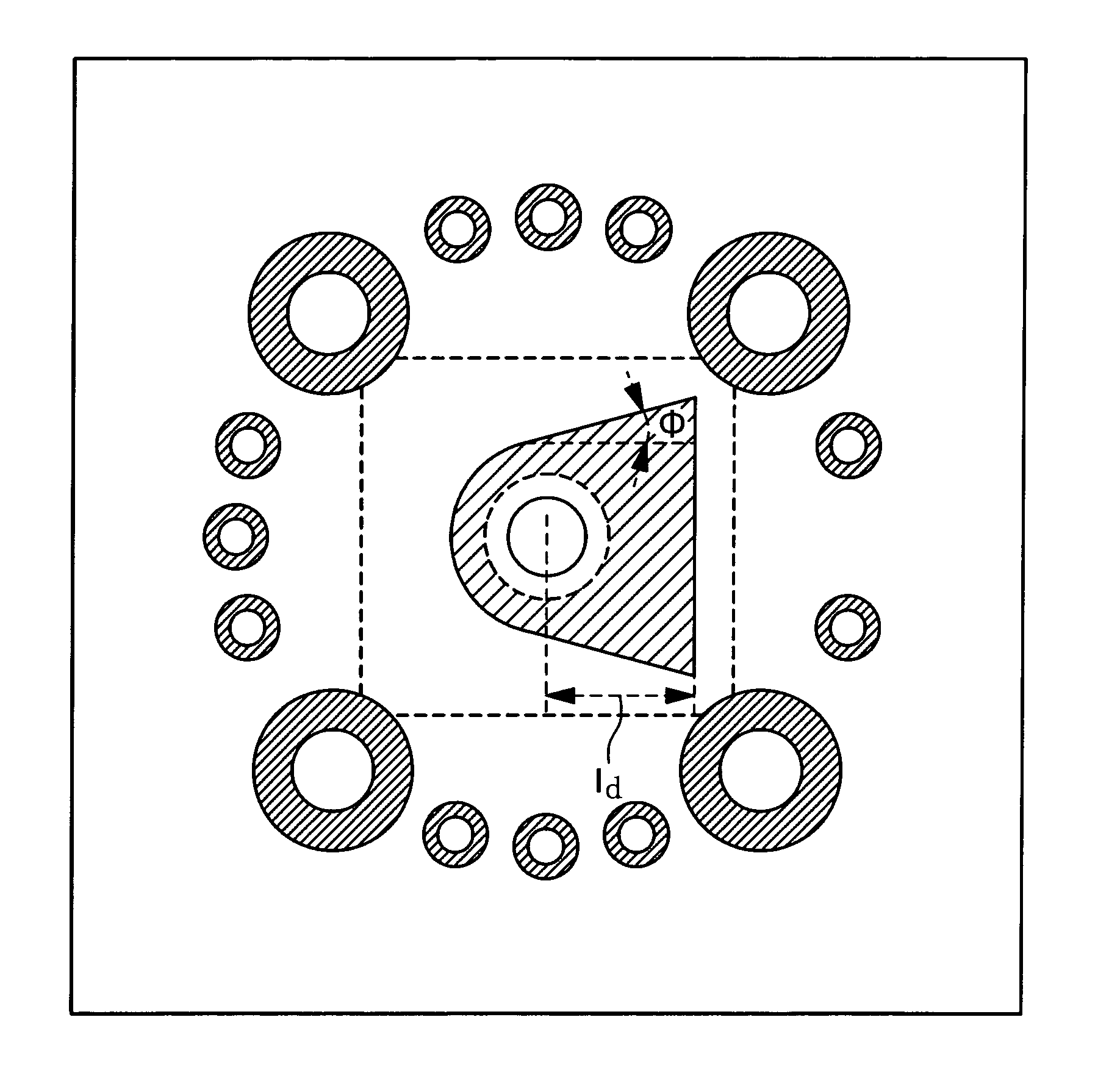
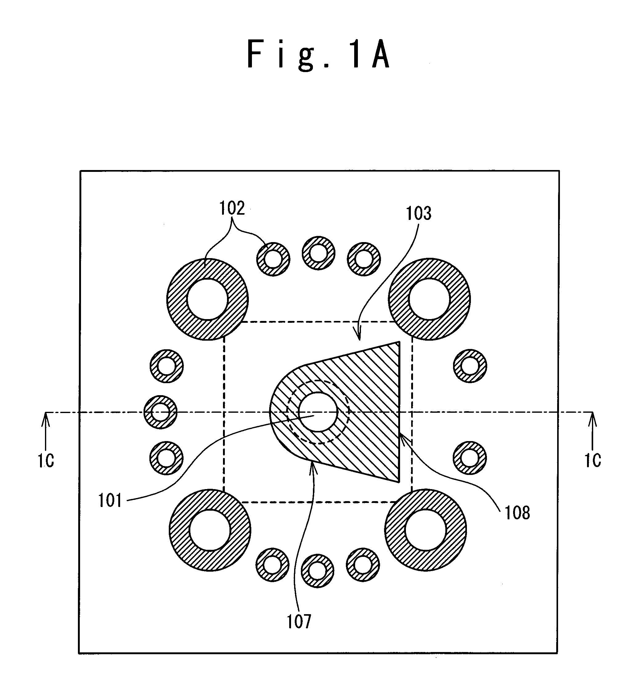
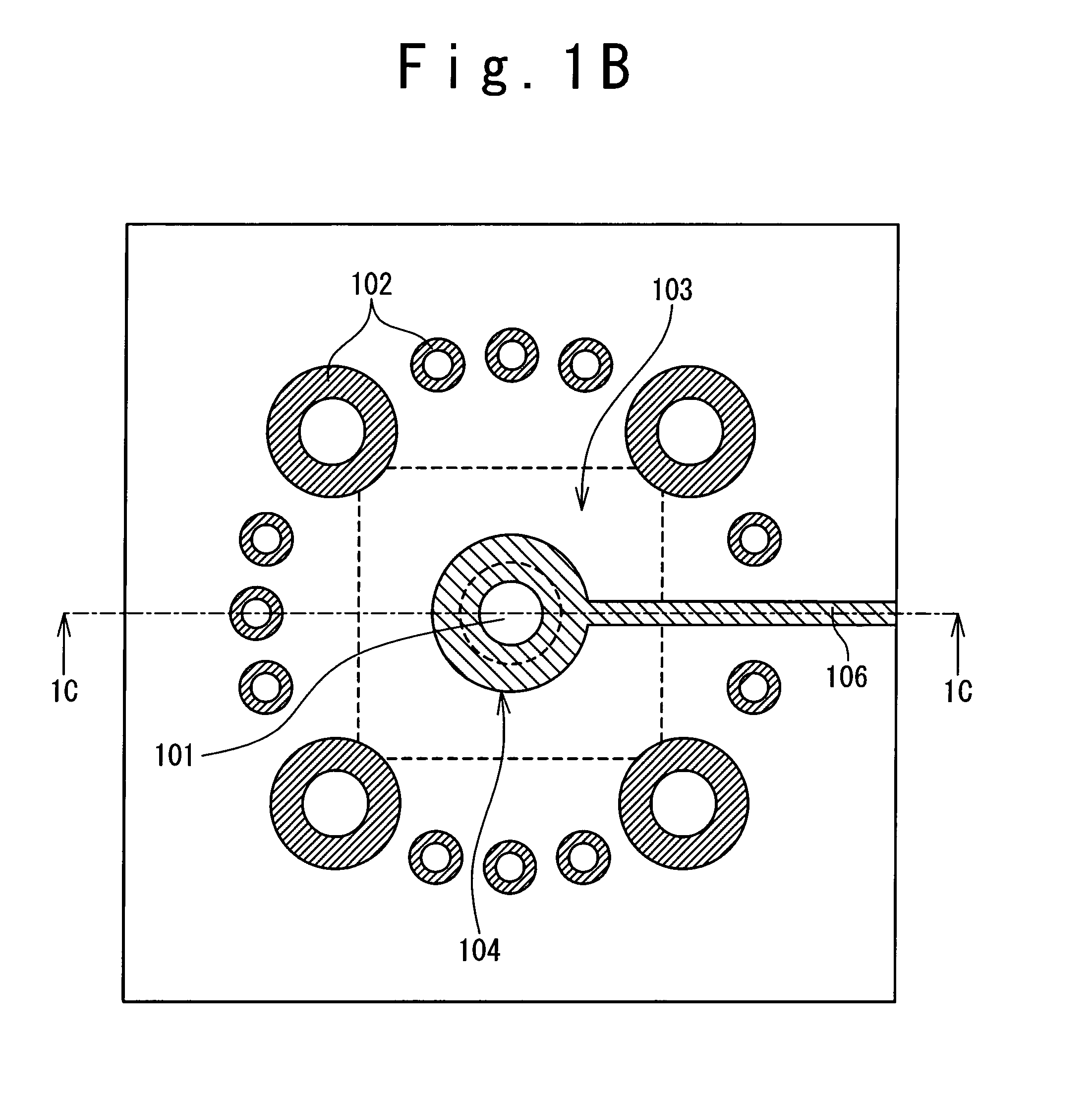
[0018]In FIGS. 1A to 1D, an example of the multi-layer substrate according to a first exemplary embodiment of the present invention is shown. The example of the multi-layer substrate presents a 10-conductor-layer printed circuit board (PCB) in which an interconnection circuit composed of a via structure and a planar transmission line connected by a multi-tier transition is disposed. It should be well understood that the number of conductor layers in the multi-layer substrate may be different and is determined depending on a specific application.

[0019]In FIGS. 1A to 1D, conductor layers 110 are separated by isolating materi...


PUM


Abstract

A multi-layer substrate includes a planar transmission line structure and a signal via, which are connected by a multi-tier transition. The multi-tier transition includes a signal via pad configured to serve for a full-value connection of the signal via and the planar transmission line; and a dummy pad connected to the signal via, formed in an area of a clearance hole in a conductor layer disposed between a signal terminal of the signal via and the planar transmission line, and isolated from the conductor layer.

Description

TECHNICAL FIELD[0001]The present invention relates to a multi-layer substrate with a high-speed interconnection structure to provide high-speed data transmission.BACKGROUND ART[0002]High-speed transmission technologies are a main theme in next-generation networking and computing systems. Their cost is an important problem to be solved to make the systems competitive in the market. A multi-layer substrate is one of the important techniques, which can satisfy both high-speed and cost-effective conditions within a predetermined frequency band and interconnection length. Electrical wiring in a planar conductor layer of the multi-layer substrate (board) can be developed on the basis of transmission lines such as microstrip lines, strip lines, and coplanar lines. Vertical interconnections in the board which serve mainly to connect planar transmission line structures disposed in different conductor layers are usually based on various types of via structures such as through-hole vias, blind...

Claims


Application Information

Patent Timeline
Patent Type & Authority Patents(United States)
IPC IPC(8): H05K1/11
CPCH05K1/0219H05K1/0222H05K1/0245H05K1/0251H05K1/116H05K3/429H05K2201/09236H05K2201/09454H05K2201/09618H05K2201/09636H05K2201/09718H05K2201/09781
Inventor KUSHTA, TARAS
Owner NEC CORP
Learn More