
Pneumatic tire with tread having cutaway portions formed in center rib

Active Publication Date: 2013-07-02
YOKOHAMA RUBBER CO LTD
View PDF41 Cites 5 Cited by
  • Summary
  • Abstract
  • Description
  • Claims
  • Application Information

AI Technical Summary

Benefits of technology

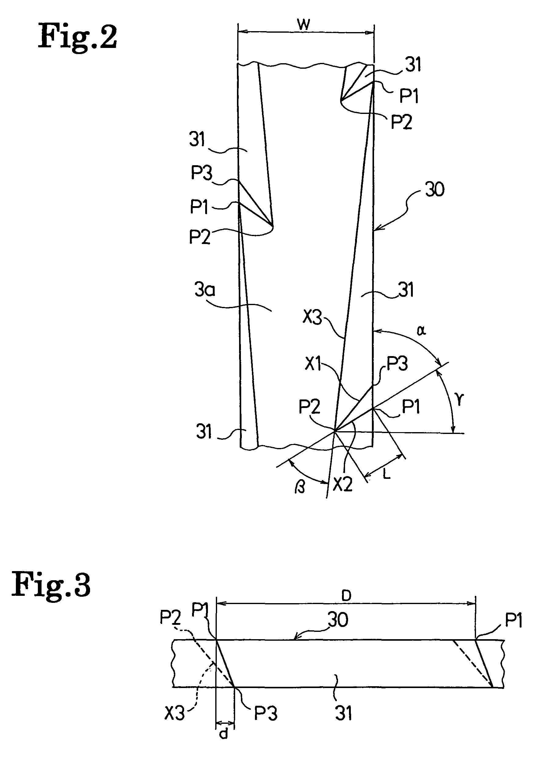
The invention is a pneumatic tire with a tread pattern that improves both on-ice and wet performance. The tire has a center rib in the center region of the tread, shoulder block rows in the shoulder regions, and intermediate blocks between the center rib and shoulder blocks. The ratio of groove area to the tire contact width is increased gradually from the center region to the shoulder regions, providing better on-ice performance. The tire also has plural sipes and cutaway portions in the center rib, which improve on-ice braking performance and driving stability. The cutaway portions have an acute angle portion and a second contour line that extends in both the tire-width and circumferential directions, with a shorter length and a narrower angle. Overall, the tire achieves both good on-ice and wet performance.

Problems solved by technology

There is, however, a problem that simply reducing the ratio of groove area may impair the drain function and thereby lower the wet performance.

Method used


Image

  • Pneumatic tire with tread having cutaway portions formed in center rib
  • Pneumatic tire with tread having cutaway portions formed in center rib
  • Pneumatic tire with tread having cutaway portions formed in center rib

Examples


examples

[0034]A pneumatic tire having a tire size of 225 / 65R17 and a tread pattern illustrated in FIG. 1 (Example 1) and a pneumatic tire having the same tire size and a tread pattern illustrated in FIG. 4 (Example 2) were fabricated. A pneumatic tire having the same size and a tread pattern illustrated in FIG. 5 (Conventional Example) was fabricated for comparative purposes. In the pneumatic tire of Conventional Example, each long block formed in each intermediate block row has a tire-circumferential-direction length equivalent to each three of the blocks included in each shoulder block row.

[0035]An assessment using these tires was conducted by an assessment method given below on: the braking performance on ice; the braking performance on a wet road surface; and the drain performance on a wet road surface. Table 1 shows the assessment results.

Braking Performance on Ice

[0036]Each of the tested tires was fitted onto a wheel with a rim size of 17×7J and then the wheel with the test tire was m...


PUM


Abstract

A pneumatic tire includes a pair of first circumferential main grooves formed in the center region of a tread, a pair of second circumferential main grooves formed respectively outward of the corresponding first main grooves, a plurality of first lug grooves which each extend from one of the two shoulder ends of the tread inward in the tire-width direction and communicate with the corresponding first main groove, a plurality of second lug grooves alternately arranged in the tire circumferential direction which each extend from one of the two shoulder ends of the tread inward in the tire-width direction but do not communicate with the corresponding first main groove, a center rib defined between the pair of first main grooves and extends continuously in the tire circumferential direction, a shoulder block row defined between each of the second main grooves and a corresponding one of the shoulder ends and includes a plurality of blocks, and an intermediate block row defined between each of the first main grooves and a corresponding one of the second main grooves. Each intermediate block row includes long blocks each of which has a tire-circumferential-direction length equivalent to the total length of each two blocks included in the corresponding shoulder block row.

Description

CROSS-REFERENCE TO RELATED APPLICATIONS[0001]The present application is a U.S. National phase of, and claims priority based on PCT / JP2008 / 060521, filed 09 June 2008, which, in turn, claims priority from Japanese patent application 2007-154989, filed 12 June 2007. The entire disclosure of each of the referenced priority documents is incorporated herein by reference.TECHNICAL FIELD[0002]The invention relates to a pneumatic tire used suitably as a winter tire. More specifically, the invention relates to a pneumatic tire capable of achieving both good on-ice performance and good wet performance.BACKGROUND ART[0003]A tread pattern employed for many conventional winter tires, such as studless tires, is a block pattern with plural sipes formed in each block so as to extend in the tire-width direction (see, for example, Patent Document 1).[0004]Decreasing the ratio of groove area thereby increasing the contact area is an effective method of improving on-ice performance of the tire of the ab...

Claims


Application Information

Patent Timeline
IPC IPC(8): B60C11/03B60C11/12
CPCB60C11/0302B60C11/0309B60C11/12B60C11/033B60C11/1315B60C2011/0388B60C2011/1213B60C2011/1295
Inventor YAMAKAWA, TAKAHIRO
Owner YOKOHAMA RUBBER CO LTD
Learn More