Motorized equipment
a motor and equipment technology, applied in the direction of magnetic circuit rotating parts, magnetic circuit shape/form/construction, transportation and packaging, etc., can solve the problems of increasing the manufacturing cost of the motor, increasing the body size in a radial direction, increasing etc., to and reduce the axial body size of the motorized equipment
- Summary
- Abstract
- Description
- Claims
- Application Information
AI Technical Summary
Benefits of technology
Problems solved by technology
Method used
Image
Examples
first embodiment
[0052](First Embodiment)
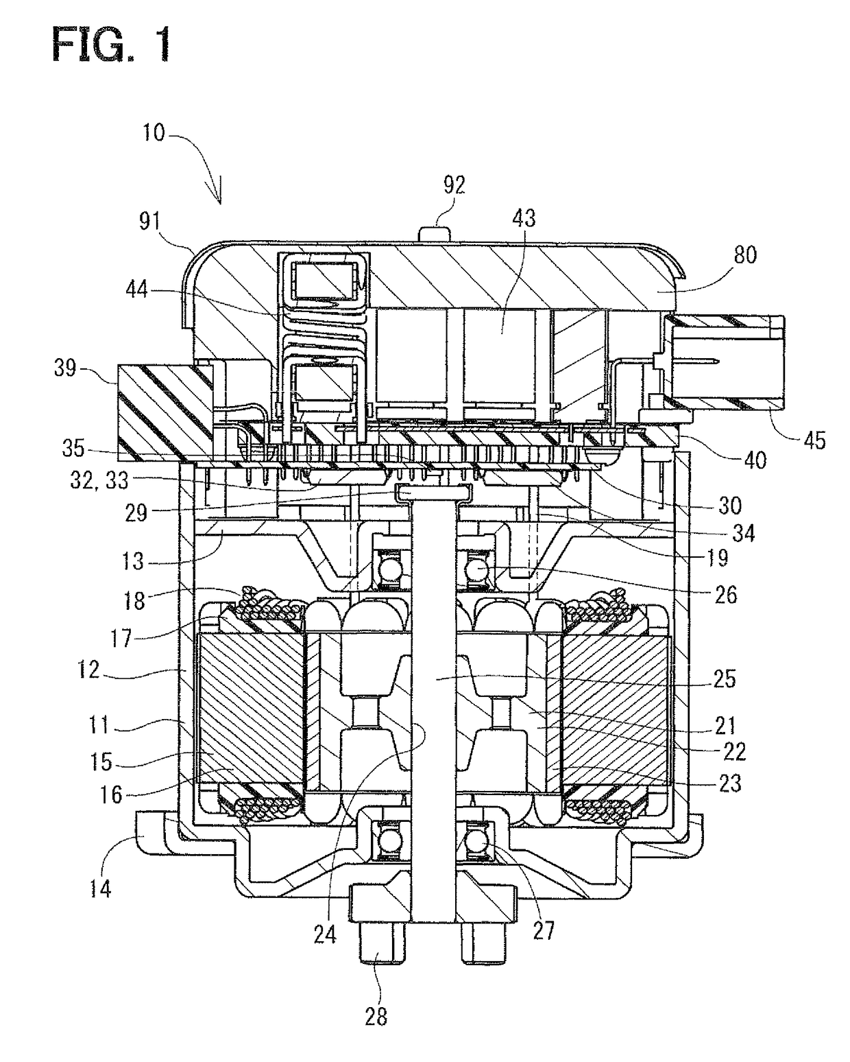
[0053]FIGS. 1 to 19 are diagrams each showing a motorized equipment according to a first embodiment of the present invention. The motorized equipment 10 according to the present embodiment is a brushless motor used for electric power steering. As shown in FIG. 6, the motorized equipment 10 meshes with a gear 2 of a column shaft 1. The motorized equipment 10 performs normal rotation and reverse rotation based on a vehicle speed signal, which is transmitted from CAN and the like, and a torque signal outputted from a torque sensor 4, which senses steering torque of a steering 3. Thus, the motorized equipment 10 generates a force for assisting steering.
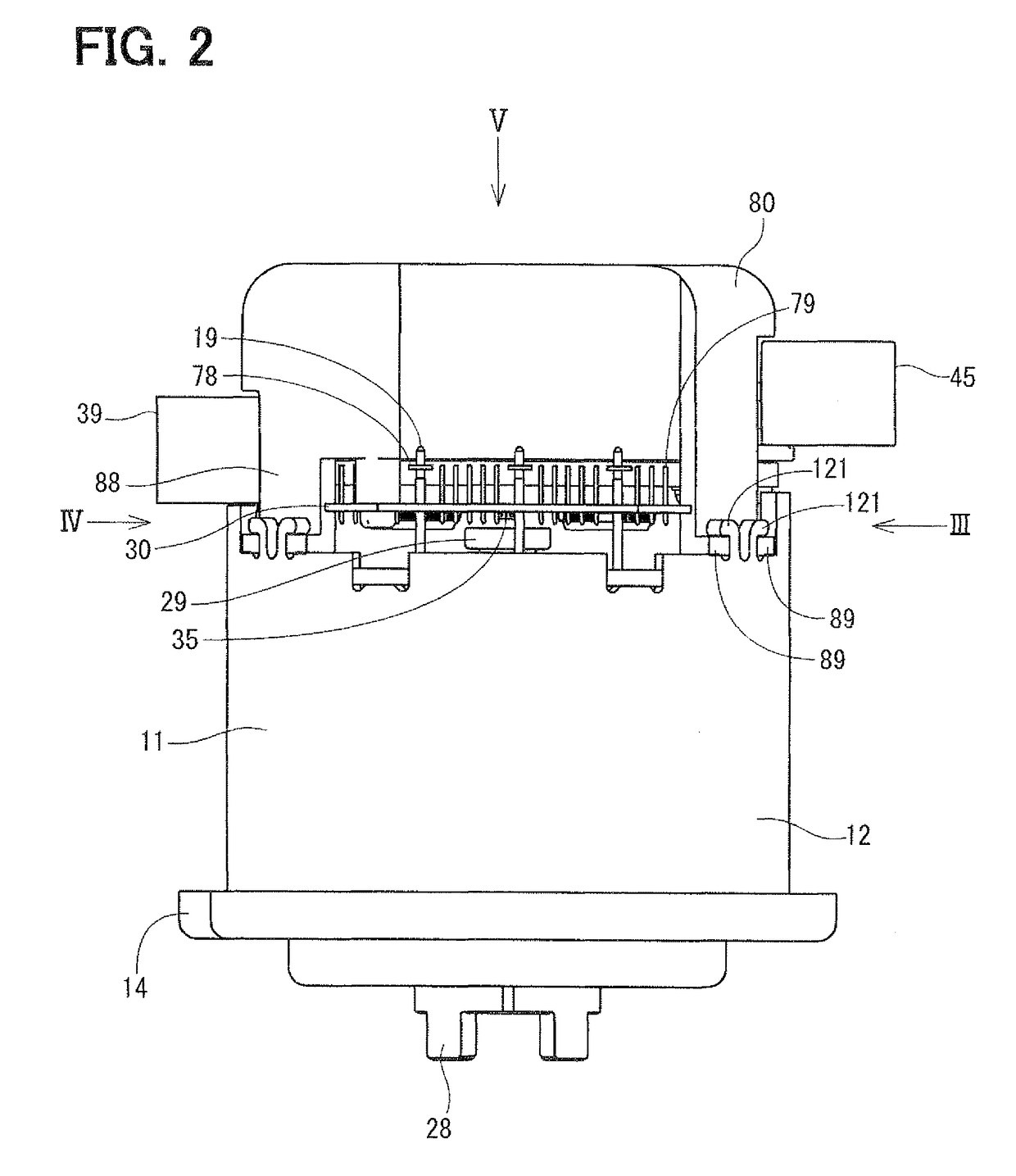
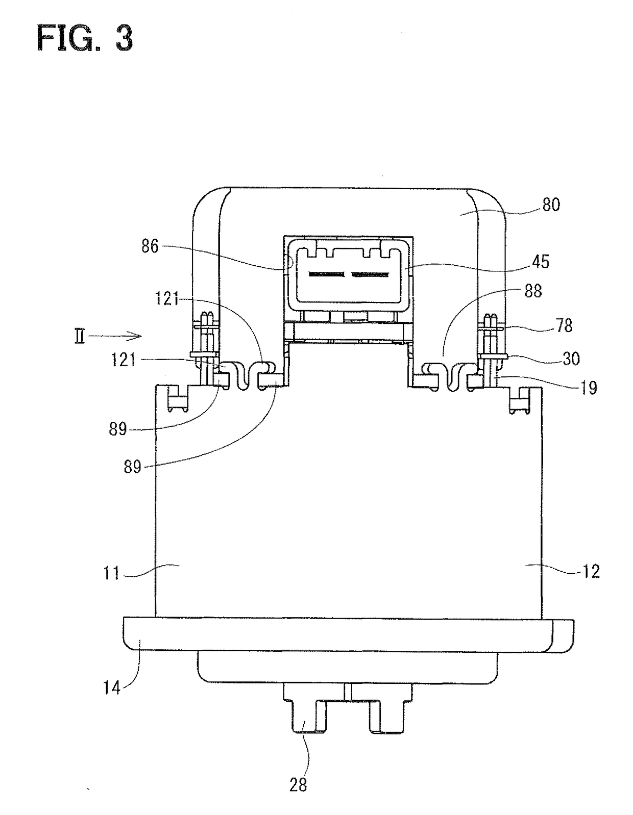
[0054]FIG. 1 is a cross-sectional view showing the motorized equipment 10 according to the present embodiment. FIGS. 2 to 5 are views each showing outer appearance of the motorized equipment 10 according to the present embodiment. FIG. 7 is an exploded perspective view showing the motorized equipment 10 according t...
second embodiment
[0087](Second Embodiment)
[0088]Next, a second embodiment of the present invention will be described. A motorized equipment 10 according to the present embodiment is shown in FIGS. 20 and 21. The motorized equipment 10 according to the present embodiment has a shield member 93 between the position sensor 35 and the power module 40. The shield member 93 is made of a material such as iron having high magnetic permeability.
[0089]A large current supplied from the battery 5 flows through the wirings 70-75 of the power module 40 as shown by an arrow mark A in FIG. 21. Therefore, an electromagnetic field is generated as shown by arrow marks B. If the electromagnetic field acts on the position sensor 35, there is a possibility that an error arises in the signal outputted from the position sensor 35.
[0090]Regarding this point, in the present embodiment, the electromagnetic field generated by the large current flowing through the wirings 70-75 of the power module 40 flows along the shield memb...
third embodiment
[0091](Third Embodiment)
[0092]Next, a third embodiment of the present invention will be described. FIG. 22 shows a motorized equipment according to the present embodiment. In the present embodiment, a shield member 94 is formed in the shape of a flat plate. Thus, the control board 30 can be shielded over a wide area and a processing cost of the shield member 94 can be reduced.
PUM
 Abstract
Description
Claims
Application Information
 - R&D
- Intellectual Property
- Life Sciences
- Materials
- Tech Scout
- Unparalleled Data Quality
- Higher Quality Content
- 60% Fewer Hallucinations
Browse by: Latest US Patents, China's latest patents, Technical Efficacy Thesaurus, Application Domain, Technology Topic, Popular Technical Reports.
© 2025 PatSnap. All rights reserved.Legal|Privacy policy|Modern Slavery Act Transparency Statement|Sitemap|About US| Contact US: help@patsnap.com


