Water permeable traffic bearing system, method and drainage joint for use with same

a technology of traffic bearings and drainage joints, which is applied in the direction of paving gutters/kerbs, roads, constructions, etc., can solve the problems of unsatisfactory retention ponds, overloading antiquated wastewater treatment systems, and already relatively labor-intensive construction of traffic bearing surfaces

Active Publication Date: 2013-06-25
BIO MICROBICS
View PDF22 Cites 6 Cited by
  • Summary
  • Abstract
  • Description
  • Claims
  • Application Information

AI Technical Summary

Problems solved by technology

Substrates covered over with a layer of concrete or asphalt tend to shed water quite rapidly, causing or exacerbating flooding, and sometimes overloading antiquated wastewater treatment systems in response to precipitation events.
While relatively simple and straightforward, time and construction expense, as well as safety and even wildlife control issues tend to make retention ponds undesirable in many instances.
On the one hand, construction of traffic bearing surfaces is already a relatively labor intensive process, requiring significant expense.
Introducing exotic materials, and often requiring their installation in a fairly precisely prescribed manner and / or under tightly specified environmental conditions, can result in excessive construction costs.
On the other hand, such materials may have inherent properties inferior to certain conventional materials such as concrete, asphalt paving material, and brick.

Method used


Image

  • Water permeable traffic bearing system, method and drainage joint for use with same
  • Water permeable traffic bearing system, method and drainage joint for use with same
  • Water permeable traffic bearing system, method and drainage joint for use with same

Examples


Embodiment Construction

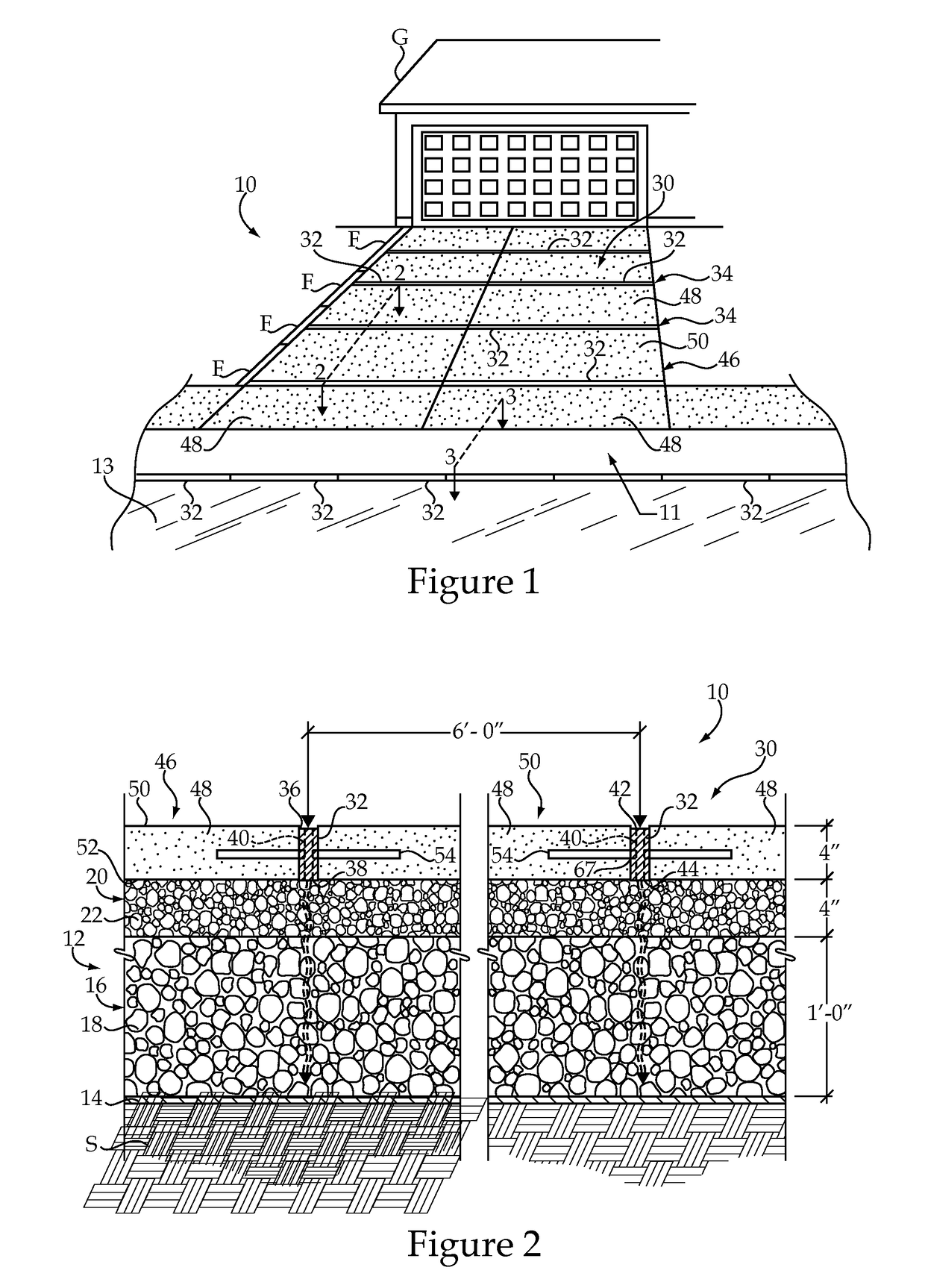
[0023]Referring to FIG. 1, there is shown a water permeable traffic bearing system 10 according to one embodiment. System 10 is shown in the context of a residential driveway system, however, the present disclosure is not thereby limited and may also be applied to sidewalks, roads, parking lots and essentially any other man made system for bearing pedestrian or vehicular traffic. As will be further apparent from the following description, system 10 may be uniquely configured to enable its water permeability to be tuned in response to various factors.

[0024]Referring also to FIG. 2, there is shown a sectioned view taken along line 2-2 of FIG. 1. System 10 may include a compound water permeable base 12 including a geotextile fabric 14 contacting a native substrate S. Substrate S may include an undisturbed soil substrate, including a sandy soil substrate, a clayey soil substrate, a high organic matter topsoil, or any other native soil, rock, or mixtures thereof. Water permeable base 12 ...


PUM

PropertyMeasurementUnit
total surface areaaaaaaaaaaa
volumeaaaaaaaaaa
volumeaaaaaaaaaa

Abstract

Making a water permeable traffic bearing system includes preparing a compound water permeable base in contact with a native substrate, and installing a drainage system having a plurality of elongate drainage joints over the prepared water permeable base. Each of the drainage joints defines a plurality of vertical drainage conduits opening at upper and lower sides and in fluid communication with a storage volume defined by the water permeable base. Making the water permeable traffic bearing system further includes forming a segmental mat having a plurality of water impermeable surface pads abutting the plurality of drainage joints, at least in part by filling voids extending horizontally between the drainage joints with a curable paving material, and curing the paving material within the voids, in contact with each of the water permeable base and the drainage joints. Installing the drainage system further includes tuning precipitation handling of the traffic bearing system, at least in part by setting a spacing and a number of the drainage joints responsive to, a water throughput factor of the traffic bearing system and a structural factor of the segmental mat. The drainage joints may have upwardly and downwardly oriented legs joined via a bridge in an H-configuration.

Description

[0001]This application claims the benefit of U.S. Provisional Patent Application Nos. 61 / 480,025, filed Apr. 28, 2011, and 61 / 372,239, filed Aug. 10, 2010.TECHNICAL FIELD[0002]The present disclosure relates generally to traffic bearing systems such as driveways, sidewalks, parking lots and roadways, and relates more particularly to an in situ drainage joint for a water-permeable traffic bearing system positionable between water impermeable surface pads.BACKGROUND[0003]Over many decades, civil engineering endeavors have altered naturally occurring drainage patterns. Transportation and other infrastructure projects are notable examples, typically transforming areas of land from a permeable state capable of absorbing and relatively slowly discharging large volumes of water into impermeable roads, parking lots and the like. Substrates covered over with a layer of concrete or asphalt tend to shed water quite rapidly, causing or exacerbating flooding, and sometimes overloading antiquated ...

Claims


Application Information

Patent Timeline
Patent Type & Authority Patents(United States)
IPC IPC(8): E01F5/00
CPCE01C3/00E01C9/001E01C11/06E01F5/00E01C11/106E01C11/224E01C11/08
Inventor WHITE, BRYAN
Owner BIO MICROBICS
Why Eureka
Try Eureka