
Display illumination response time compensation system and method

a compensation system and display technology, applied in the field of digital video presentations, can solve the problems of adversely affecting the clear and timely presentation of images, limitations of display device response characteristics, and complex digital video presentations, so as to reduce adverse presentation impacts, reduce image blurriness, and clear images

Active Publication Date: 2013-06-18
NVIDIA CORP
View PDF41 Cites 15 Cited by
  • Summary
  • Abstract
  • Description
  • Claims
  • Application Information

AI Technical Summary

Benefits of technology

This patent is about a system and method that can make digital video displays look better by compensating for delays in how the content is received and displayed. This can reduce blurring and make objects in the video move more clearly. The technology adjusts the brightness of pixels to make the video look better, and can improve image quality for viewers.

Problems solved by technology

However, digital video presentations can be very complex and often include moving objects which usually involves significant presentation illumination changes.
Limitations of display device response characteristics can adversely impact clear and timely presentation of the images.
Despite the differences in the way the high energy beams are impinged on a pixel, the format in which image information is provided to the displays is usually similar and there are typically constraints that impact rendering of an image.
For example, graphics image display devices such as a liquid crystal display (LCD) typically take a period of time to respond to pixel information.
However, there are numerous conditions that can have a significant impact on the perceptibility of the presentation.
Rapid variances in pixel data associated with moving images can cause distortions and blurriness in object presentation or pixel illumination.
A response time of a display device that is slower than a refresh rate of video pixel information can produce undesirable blurry or inaccurate presentations which usually results in a user experience that is non-immersive and unpleasant.
For example, an image of a blue car moving in front of a red building can produce a frame in which some of the pixels that should be blue and associated with the car are still red and associated with the building resulting in a distortion of the car image with the building image.
User's tend to have ever increasing demands for ever more spectacular and clearer images with better resolutions and glitches or delays in image rendering can diminish user experience and / or interaction with a video device.

Method used


Image

  • Display illumination response time compensation system and method
  • Display illumination response time compensation system and method
  • Display illumination response time compensation system and method

Examples


Embodiment Construction

[0014]Reference will now be made in detail to the preferred embodiments of the invention, examples of which are illustrated in the accompanying drawings. While the invention will be described in conjunction with the preferred embodiments, it will be understood that they are not intended to limit the invention to these embodiments. On the contrary, the invention is intended to cover alternatives, modifications and equivalents, which may be included within the spirit and scope of the invention as defined by the appended claims. Furthermore, in the following detailed description of the present invention, numerous specific details are set forth in order to provide a thorough understanding of the present invention. However, it will be obvious to one of ordinary skill in the art that the present invention may be practiced without these specific details. In other instances, well known methods, procedures, components, and circuits have not been described in detail as not to unnecessarily ob...


PUM


Abstract

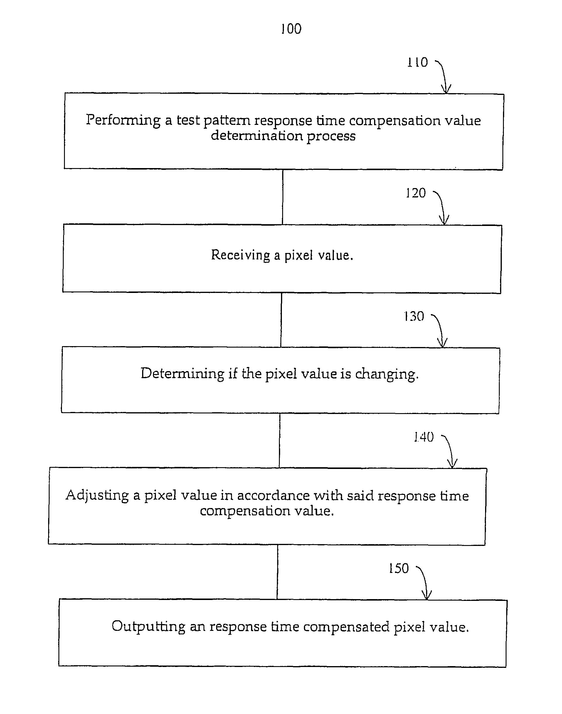
A digital video display response time compensation system and method are presented. A digital video display response time compensation system and method are utilized to direct adjustments in a display presentation. A test pattern response time compensation value determination process for establishing appropriate adjustment levels for a display is performed. A test pattern is displayed; user input on compensation to the test pattern display is received; pixel value calibration settings are determined based upon the user input; and the test pattern display appearance is altered based upon the pixel value calibration settings. After the appropriate pixel illumination adjustment values are establish a pixel value is received. The pixel value is adjusted in accordance with the response time compensation value and a response time compensated pixel value is output.

Description

FIELD OF THE INVENTION[0001]The present invention relates to the digital video presentations. More particularly the present invention relates to display compensation systems and methods.BACKGROUND OF THE INVENTION[0002]Electronic systems and circuits have made a significant contribution towards the advancement of modern society and are utilized in a number of applications to achieve advantageous results. Numerous electronic technologies such as digital computers, calculators, audio devices, video equipment, and telephone systems have facilitated increased productivity and reduced costs in analyzing and communicating data, ideas and trends in most areas of business, science, education and entertainment. Frequently, these advantageous results are realized through the use of digital video presentations. The digital video presentations typically provide information in a format that humans typically find easy to observe and digest significant amounts of data in relatively short periods o...

Claims


Application Information

Patent Timeline
Patent Type & Authority Patents(United States)
IPC IPC(8): G09G3/36
CPCG09G3/3648G09G3/006G09G2320/0252G09G2320/0285
Inventor HERZ, WILLIAM SAMUEL
Owner NVIDIA CORP
Learn More