
Machine, program product, and computer-implemented method to simulate reservoirs as 2.5D unstructured grids

a technology of unstructured grids and reservoirs, applied in seismology, water-logging instruments, and reradiation, etc., can solve problems such as faulting and fracturing of layers, simulation models can take days, and models cannot be neatly followed

Active Publication Date: 2013-06-11
SAUDI ARABIAN OIL CO
View PDF40 Cites 39 Cited by
  • Summary
  • Abstract
  • Description
  • Claims
  • Application Information

AI Technical Summary

Benefits of technology

This approach enables more accurate modeling of complex reservoirs and well geometries with fewer data points, reducing computational complexity and improving simulation accuracy while maintaining efficient data processing.

Problems solved by technology

Because reservoirs can be complex, and grid cells can number in the millions, the simulation models can take days.
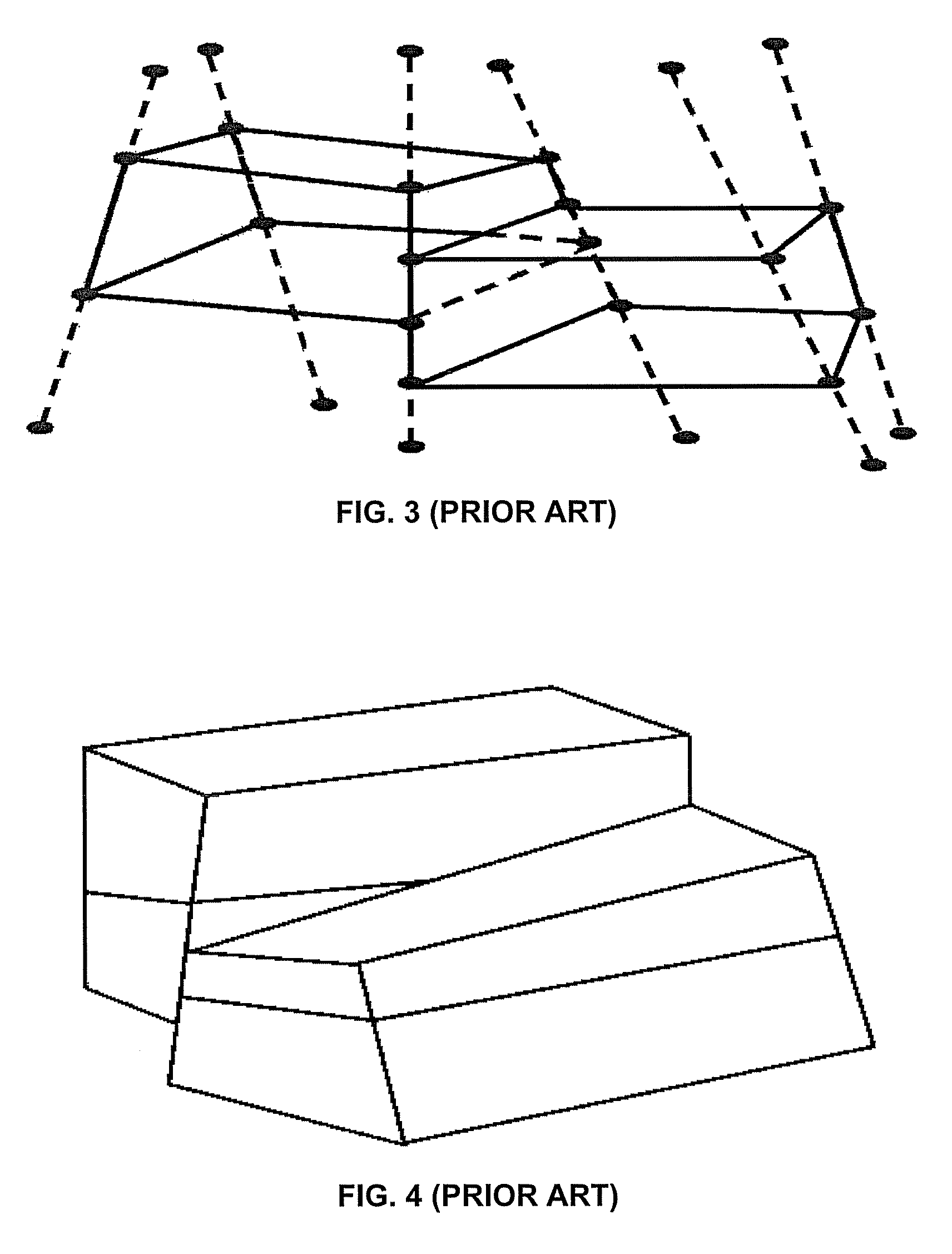
Unfortunately, reservoirs are of a sedimentary origin and have multiple layers that have thicknesses and depth variations throughout, which do not neatly follow the pattern of a structured grid.
Also, uplifting (the raising of the earth's crust) and subsidence (the lowering of the earth's crust) over geologic time can lead to faulting and fracturing of the layers.
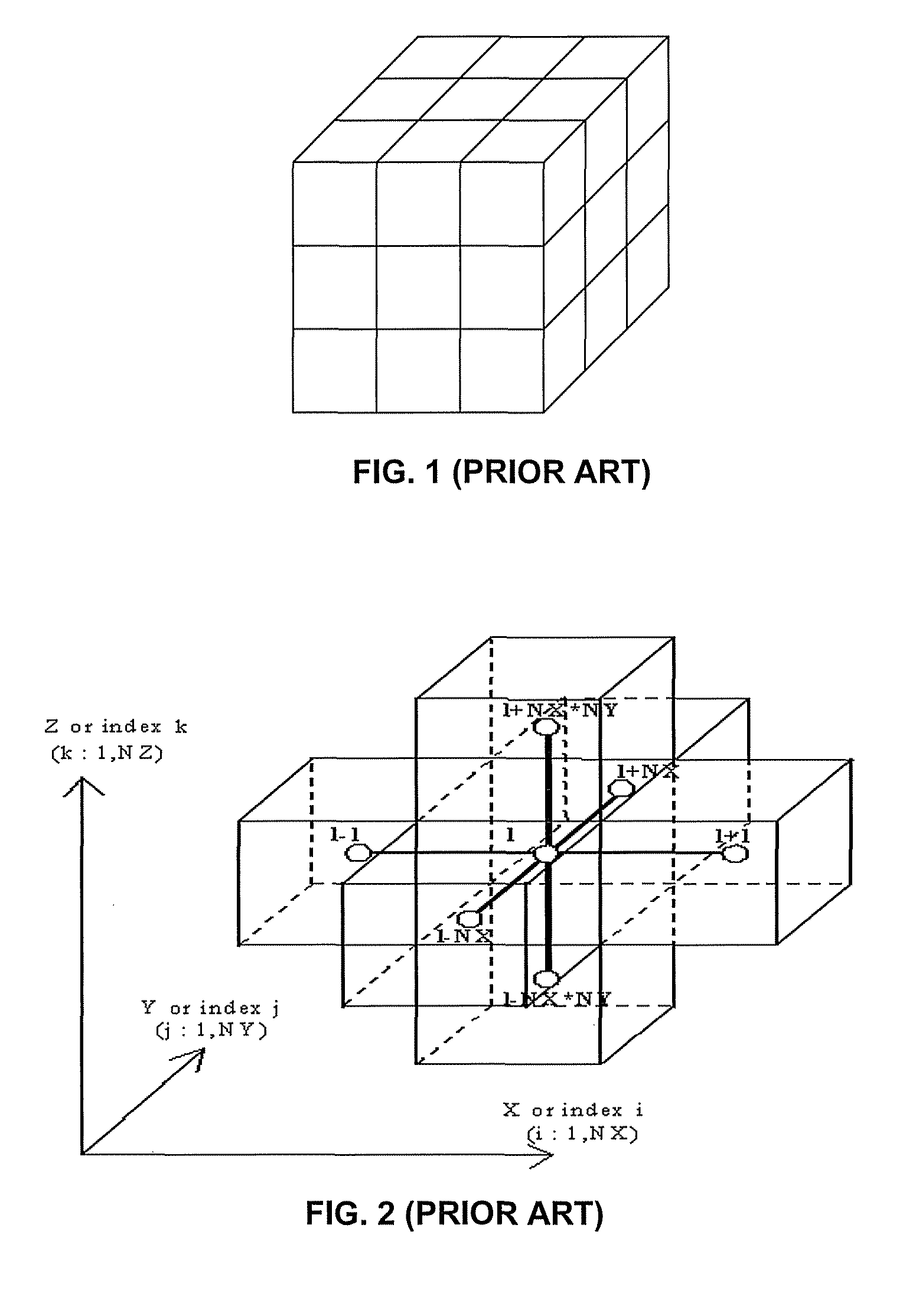
Conventional reservoir simulators that use Cartesian grids or corner point geometry (CPG) grids for reservoir simulation have difficulty, with complex geological features (including faults, pinch-outs, and, erosion) and complex well geometries (including deviated or multi-lateral wells) as shown in FIG. 6, and may generate smaller grid dimensions to account for these features.
With conventional techniques, smaller grid dimensions result in more accurate approximations of the reservoir, but at a cost of larger datasets (i.e., more data points).
Accordingly, these maps may be very complex.
Unfortunately, the global hash table for a model with, e.g., millions of cells, can overwhelm the memory of for each of the parallel computers.
In addition to the problems with prior art reservoir grids, simulating reservoirs having multi-lateral wells require more data input and use more complex algorithms, and simulation models for this types of production methods can be very cumbersome—even using the POWERS™ system.
The computational complexity of these equations is further complicated by geological model size is typically in the tens of million to hundreds of million of grid cells.
Since finding a solution to millions of partial differential equations is computationally expensive, reservoir simulation models are usually built at a coarser scale than the geologic model via a data process known as upscaling, i.e. the averaging of rock properties for a plurality of grid cells.
While computationally more efficient, upscaling renders the simulation model less accurate (and the upscaling makes the inaccuracy of the structured grid models more pronounced).

Method used


Image

  • Machine, program product, and computer-implemented method to simulate reservoirs as 2.5D unstructured grids
  • Machine, program product, and computer-implemented method to simulate reservoirs as 2.5D unstructured grids
  • Machine, program product, and computer-implemented method to simulate reservoirs as 2.5D unstructured grids

Examples


Embodiment Construction

[0043]Although the following detailed description contains many specific details for purposes of illustration, it is understood that one of ordinary skill in the art will appreciate that many examples, variations and alterations to the following details are within the scope and spirit of the invention. Accordingly, the exemplary embodiments of the invention described herein are set forth without any loss of generality to, and without imposing limitations thereon, the claimed invention.

[0044]FIGS. 8 and 9 describe a networked group of computers defining an embodiment of the machine of the instant invention. The exemplary machine consists of a pre-processing server 802 for generating and managing the reservoir grids and directing grid data into storage; a plurality of application servers 804 for receiving grid, well-production and completion data and processing reservoir simulations; file server 806 for the management and storage of simulation data, reservoir grids, geological data, w...


PUM


Abstract

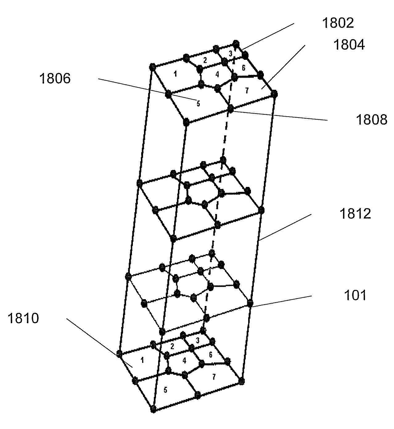
Example embodiments utilize machines to model reservoir geometry having geological layers as 2.5D unstructured grids. Example embodiments include program products to simulate a reservoir by generating a reservoir data system, performing a numerical fluid flow simulation, and visualizing the simulation. Data system embodiments include data structures to model a reservoir geometry as laterally unstructured two-dimensional (2D) grids and associated layer depths defining z-lines to thereby define a 2.5D unstructured grid, including datasets for: vertices of the grid cells for the future grid top and bottom surfaces, a number and listing of vertices for each grid cell, cell center coordinates, and vertex adjacency information using a compressed sparse row format. Computer-implemented methods include projecting external and internal boundaries onto a future grid surface; generating 2D unstructured, e.g., Voronoi, grids, for the top and bottom surfaces; and generating z-lines of depths corresponding to reservoir layers to thereby generate 2.5D unstructured grids.

Description

BACKGROUND OF THE INVENTION[0001]1. Field of the Invention[0002]The present invention relates generally to computerized simulation of hydrocarbon reservoirs, and, more particularly, to a method and data system of 2.5D unstructured grid storage, calculation, and visualization.[0003]2. Description of Related Art[0004][1] A subterranean geologic body or formation contains multi-phase, multi-component fluids, and accordingly a petroleum reservoir may contain oil, natural gas, water and several constituent compounds, that may be modeled to predict the fluid flow from a reservoir, which is also known as reservoir simulation. Reservoir simulation models may be run before or after a well is drilled to determine production rate, etc. for the various methods.[0005]Current reservoir modeling techniques create a numerical grid of the reservoir comprised of a plurality of grid cells, and process data in the finite volume of each grid cell. Because reservoirs can be complex, and grid cells can nu...

Claims


Application Information

Patent Timeline
Patent Type & Authority Patents(United States)
IPC IPC(8): G06G7/48
CPCG01V99/00G06K19/07318G06K19/07345G06T17/05G06T17/20G01V2210/663H05K1/0254H05K1/0373H05K2201/0738
Inventor MEZGHANI, MOKHLES M.FUNG, LARRY S.
Owner SAUDI ARABIAN OIL CO
Learn More