Electric drive tool

a technology of electric drive and drive shaft, which is applied in the direction of manufacturing tools, nailing tools, stapling tools, etc., can solve the problem that the prompt mode switch cannot be performed

Inactive Publication Date: 2013-06-04
MAKITA CORP
View PDF44 Cites 15 Cited by
  • Summary
  • Abstract
  • Description
  • Claims
  • Application Information

AI Technical Summary

Benefits of technology

[0018]According to another aspect of the invention, an unintended driving operat...

Problems solved by technology

Previously, one having a special switchable lever has been provided in order to switch between these ...

Method used


Image

  • Electric drive tool
  • Electric drive tool
  • Electric drive tool

Examples


Embodiment Construction

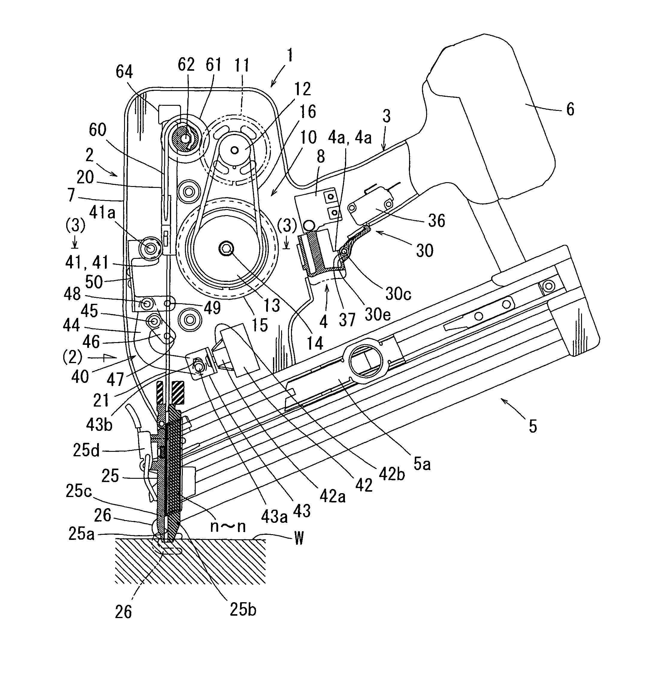
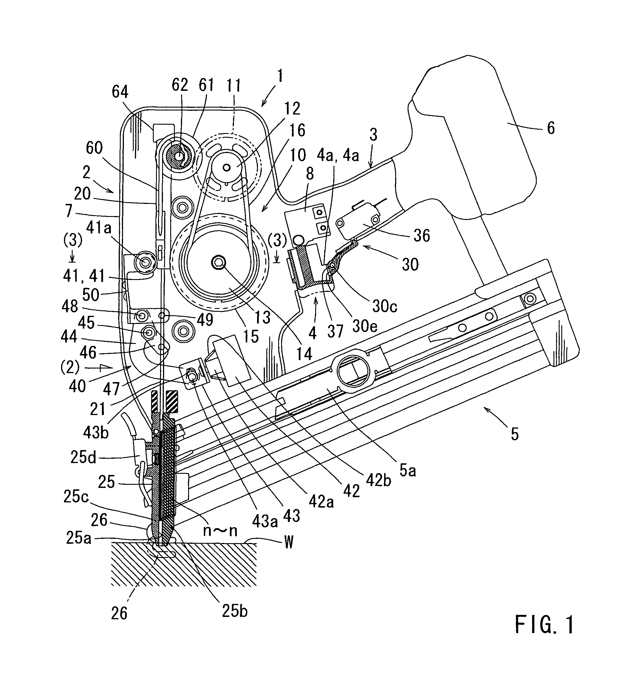
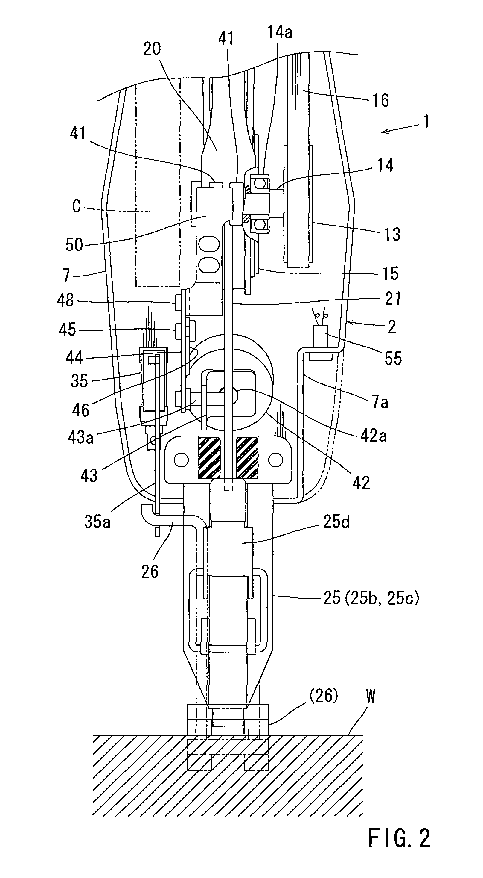
[0036]Next, an embodiment of the present invention will be described with reference to FIGS. 1 to 17. FIG. 1 and FIG. 2 show a drive tool 1 according to this embodiment. The drive tool 1 includes a body portion 2, a handle portion 3, and a magazine 5.

[0037]The body portion 2 has a configuration including a driving mechanism 10 using an electric motor 11 as a driving source provided in the interior of a body housing 7 of a substantially cylindrical resin-made two-piece structure. One nail n is struck and driven into a driven material W by the driving mechanism 10. Detailed description of the driving mechanism 10 will be given later.

[0038]The handle portion 3 is provided integrally in a state of protruding laterally from a lateral part of the body portion 2. The handle portion 3 has a two-piece structure formed integrally with a lateral part of the body housing 7. The handle portion 3 includes a trigger 4 (a switch lever of a trigger type) and a lock lever 30 which are arranged at a b...


PUM


Abstract

The electric drive tool of the invention is configured such that a lock lever is provided to reliably prevent an erroneous operation of a trigger and an operating mode can be switched by changing an operational sequence of this lock lever and a contact trip.

Description

BACKGROUND OF THE INVENTION[0001]1. Field of the Invention[0002]The present invention relates to a drive tool for driving driven members, such as nails, into a driven material using an electric motor as a drive source.[0003]2. Description of the Related Art[0004]For example, a nail driving machine generally uses compressed air as a driving source, and a large striking power can be obtained by reciprocating a piston with the compressed air. In contrast, a tool has been proposed which strikes driven members, such as nails, by reciprocating a striking driver (a striking rod) with an electric motor as a driving source. Since driving the electric motor as the driving source with a direct current power source (a battery) makes connection of an air hose and a device such as a compressor in the case of an air system to become unnecessary, usability and handling property of the driven tools can be improved.[0005]This electric drive tool has a basic configuration in which a drive wheel is rot...

Claims


Application Information

Patent Timeline
IPC IPC(8): B25C1/06
CPCB25C1/06B25C1/008
Inventor SUDA, HIDEKAZU
Owner MAKITA CORP
Why Eureka
Try Eureka