Conversion adapter

Pending Publication Date: 2022-03-24
TOYOTA JIDOSHA KK
View PDF0 Cites 0 Cited by
  • Summary
  • Abstract
  • Description
  • Claims
  • Application Information

AI Technical Summary

Benefits of technology

The present patent aims to prevent unintended operations when using conversion adapters to connect charging equipment and inlets of vehicles. The connection prevention mechanism keeps the first end of the conversion adapter not connectable until the second end is connected to the inlet, ensuring that only the second end is connected and the first end is not exposed. This prevents situations where the user may accidentally connect the first end to the charging equipment, leaving the second end unconnected and exposed. The technical effects of this mechanism include improved safety and reliability when using conversion adapters for charging vehicles.

Problems solved by technology

If the charging standard that the charging cable follows and the charging standard that the inlet follows are incompatible, the charging cable and the inlet are not connectable to each other.
Although the charging cable of the charging equipment is connected to one end (the first end) of the conversion adapter, the charging equipment may erroneously determine that the charging cable is connected to the vehicle.

Method used


Image

  • Conversion adapter
  • Conversion adapter
  • Conversion adapter

Examples


embodiment 1

[0022]

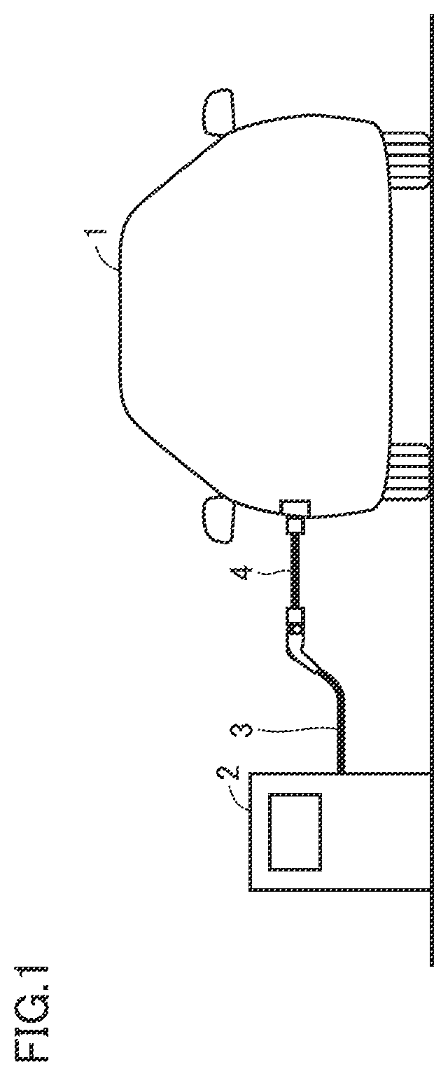
[0023]FIG. 1 is a diagram showing a situation in which plug-in charging is performed on a vehicle at a charging station, using a conversion adapter. Referring to FIG. 1, for the plug-in charging of a vehicle 1, the vehicle 1 and a charging station 2 are electrically connected together by a charging cable 3 and a conversion adapter 4.

[0024]The vehicle 1 is capable of plug-in charging, and, is, specifically, an electric vehicle (EV), a plug-in hybrid vehicle (PHV), a fuel cell vehicle (FCV), etc. The charging station (charging equipment) 2 is, for example, a public charging station provided at an outside-the-home location of the vehicle 1. A charging cable 3 extends from the charging station 2.

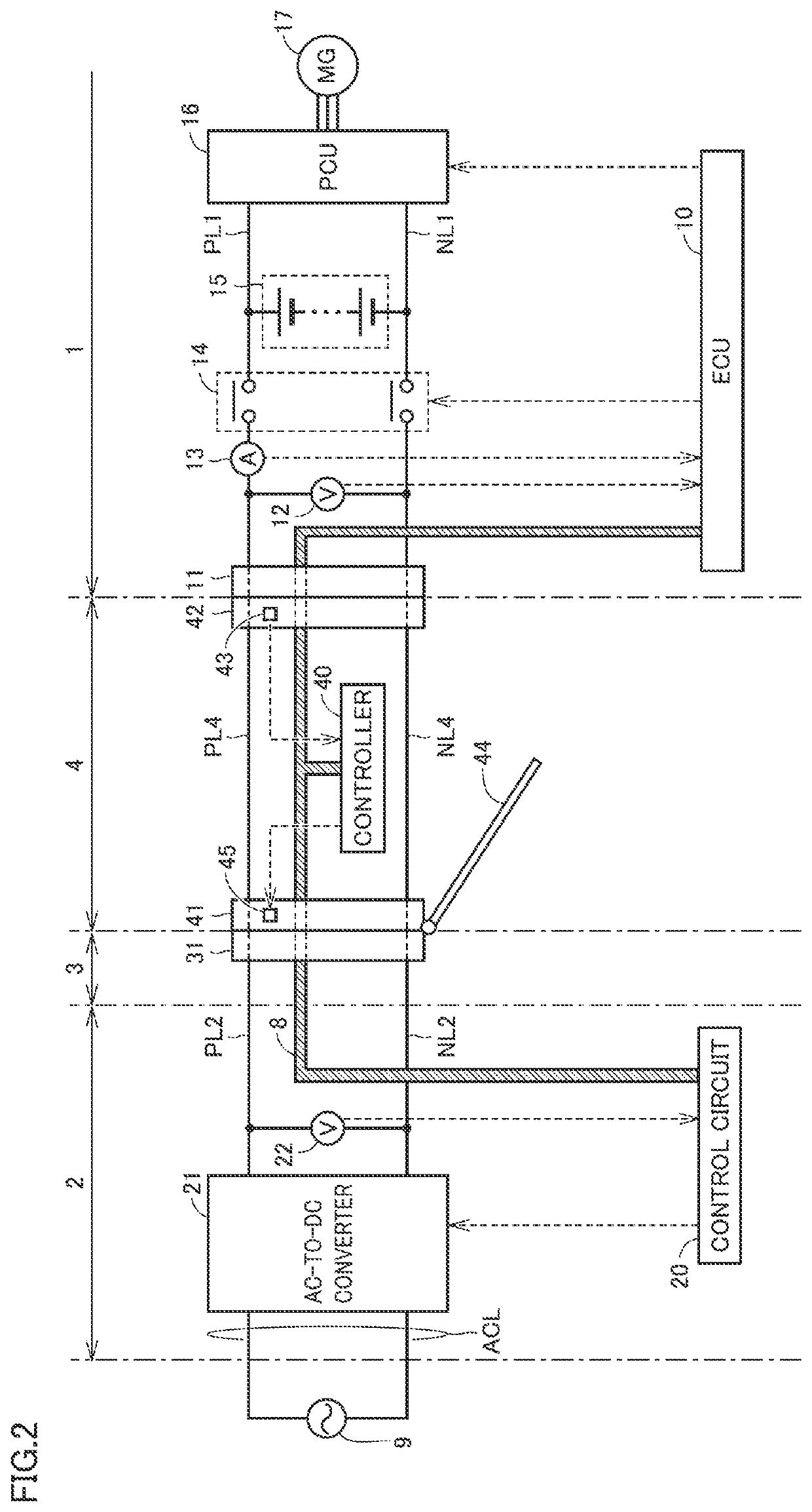
[0025]The vehicle 1 conforms to one charging standard for plug-in charging. The charging station 2 conforms to another charging standard for plug-in charging. There is no compatibility between the charging standard to which the vehicle 1 conforms, and the charging standard to which the cha...

embodiment 2

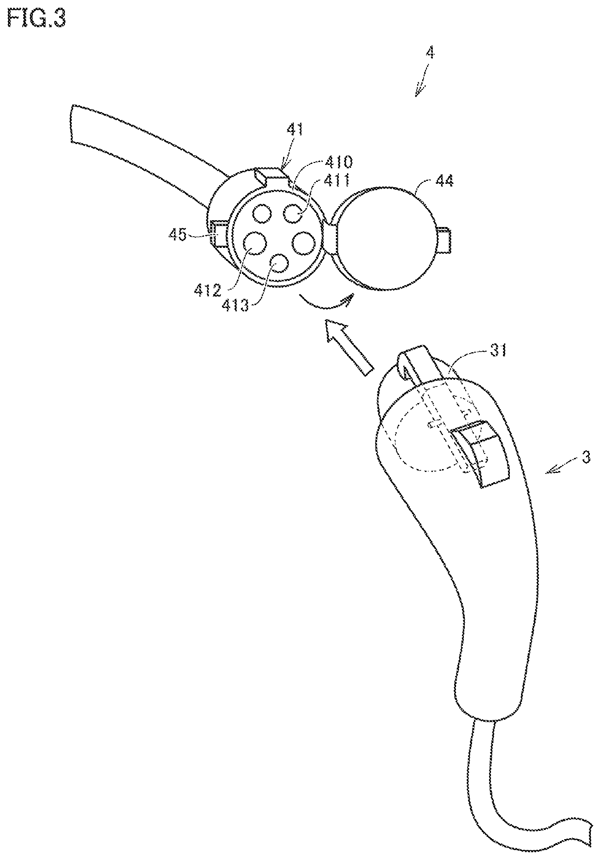
[0060]Embodiment 1 has been described with reference to providing the conversion adapter 4 with the mechanisms, including the lid 44 and the lock device 45. However, the configuration of the mechanisms added to the conversion adapter is not limited thereto, insofar as the connection order of the connectors at the opposing ends of the conversion adapter 4 can be uniquely defined. Embodiment 2 is now described with reference to a movable pin as an additional element to the conversion adapter.

[0061]FIG. 5 is a block diagram schematically showing a configuration of a vehicle, a charging station, a charging cable, and a conversion adapter, according to Embodiment 2. Referring to FIG. 5, a conversion adapter 4A differs from the conversion adapter 4 according to Embodiment 1 (see FIG. 2) in that the conversion adapter 4A includes movable pins 46 and a drive device 47, in addition to a lid 44 and a lock device 45. The vehicle 1, a charging station 2, and a charging cable 3 each have the sam...


PUM


Abstract

A conversion adapter is configured to be connected between a charging cable extending from a charging station and an inlet included in a vehicle. The conversion adapter includes a cable connector configured to be connected to the charging cable, and a vehicle connector configured to be connected to the inlet. The cable connector includes: a power terminal that receives supply of a charging power from the charging station via the charging cable; and a lid and a lock device that are configured to mechanically prevent a connection between the power terminal and the charging cable. The lid and the lock device prevent the connection between the charging cable and the power terminal until the vehicle connector and the inlet are connected together, and removes prevention of the connection between the charging cable and the power terminal after the vehicle connector and the inlet are connected together.

Description

CROSS REFERENCE TO RELATED APPLICATIONS[0001]This nonprovisional application claims priority to Japanese Patent Application No. 2020-158445 filed on Sep. 23, 2020 with the Japan Patent Office, the entire content of which is hereby incorporated by reference.BACKGROUNDField[0002]The present disclosure relates to a conversion adapter, and, more particularly, to a conversion adapter used for plug-in charging of a vehicle.Description of the Background Art[0003]Vehicles capable of plug-in charging are getting popular. For plug-in charging, a charging cable extending from charging equipment is connected to an inlet of a vehicle.[0004]The charging cable and the inlet each have a shape according to the charging standard for the plug-in charging. However, in recent years, various charging standards exist. If the charging standard that the charging cable follows and the charging standard that the inlet follows are incompatible, the charging cable and the inlet are not connectable to each other...

Claims


Application Information

Patent Timeline
IPC IPC(8): B60L53/16B60L53/18H01R31/06H02J7/00
CPCB60L53/16B60L53/18B60L2210/30H02J7/0036H01R31/065H01R13/64H02J7/0045H01R13/453H01R13/70Y02T10/70Y02T10/7072Y02T90/14
Inventor MOTOHIRA, AKITO
Owner TOYOTA JIDOSHA KK
Why Eureka
Try Eureka