Safety for a repeating rifle

a repeating rifle and safety technology, applied in the direction of safety arrangement, weapons, weapons, etc., can solve the problems of large operating force and relatively high friction of cooperating parts, and achieve the effect of compact construction, high degree of safety, and small force expenditur

Inactive Publication Date: 2012-06-28
BLASER FINANZHLDG
View PDF32 Cites 0 Cited by
  • Summary
  • Abstract
  • Description
  • Claims
  • Application Information

AI Technical Summary

Benefits of technology

[0003]An object of the invention is to create a safety of the type mentioned above that has a high degree of safety with an extremely compact construction and a small expenditure of force.
[0004]In the safety according to the invention, the locking element is constructed as a safety lever rotatable about a transverse pin, with a control part engaging with a control groove on the firing pin nut. Thereby an extremely compactly constructed and conveniently operable safety with a high safety standard can be achieved. This safety can be safely used even with a low exertion of force, whereby the handling of the repeating rifle can be improved.
[0007]In order to prevent an unintended operation of the safety slider, an additional securing element for detachably holding the safety slider in the safety and unsecured positions is provided on the safety slider. The securing element can be formed as a pushbutton displaceable in the safety slider, for example. In a particularly expedient configuration, the safety slider is constructed in such a manner that a rear part of the securing element, as viewed in the direction of movement of the safety slider into the upper, unsecured position, is flush with the upper side of the safety slider or slightly offset from the inside, while a front part projects relative to the upper side of the safety slider 4. Thereby an unintended actuation of the securing element 6 can be avoided.
[0008]In another advantageous embodiment of the invention, a chamber connected to the lock comprises a locking groove for locking engagement with a protrusion on a sear arm in the safety position of the safety slider. A rotation and therefore an opening of the chamber can be prevented by the engagement of the protrusion with the locking groove of the chamber. Additional safety can be achieved in this manner.

Problems solved by technology

Large operating forces are necessary, however, because the transmission ratio in this case is low and the friction of the cooperating parts is relatively high.

Method used


Image

  • Safety for a repeating rifle
  • Safety for a repeating rifle
  • Safety for a repeating rifle

Examples


Embodiment Construction

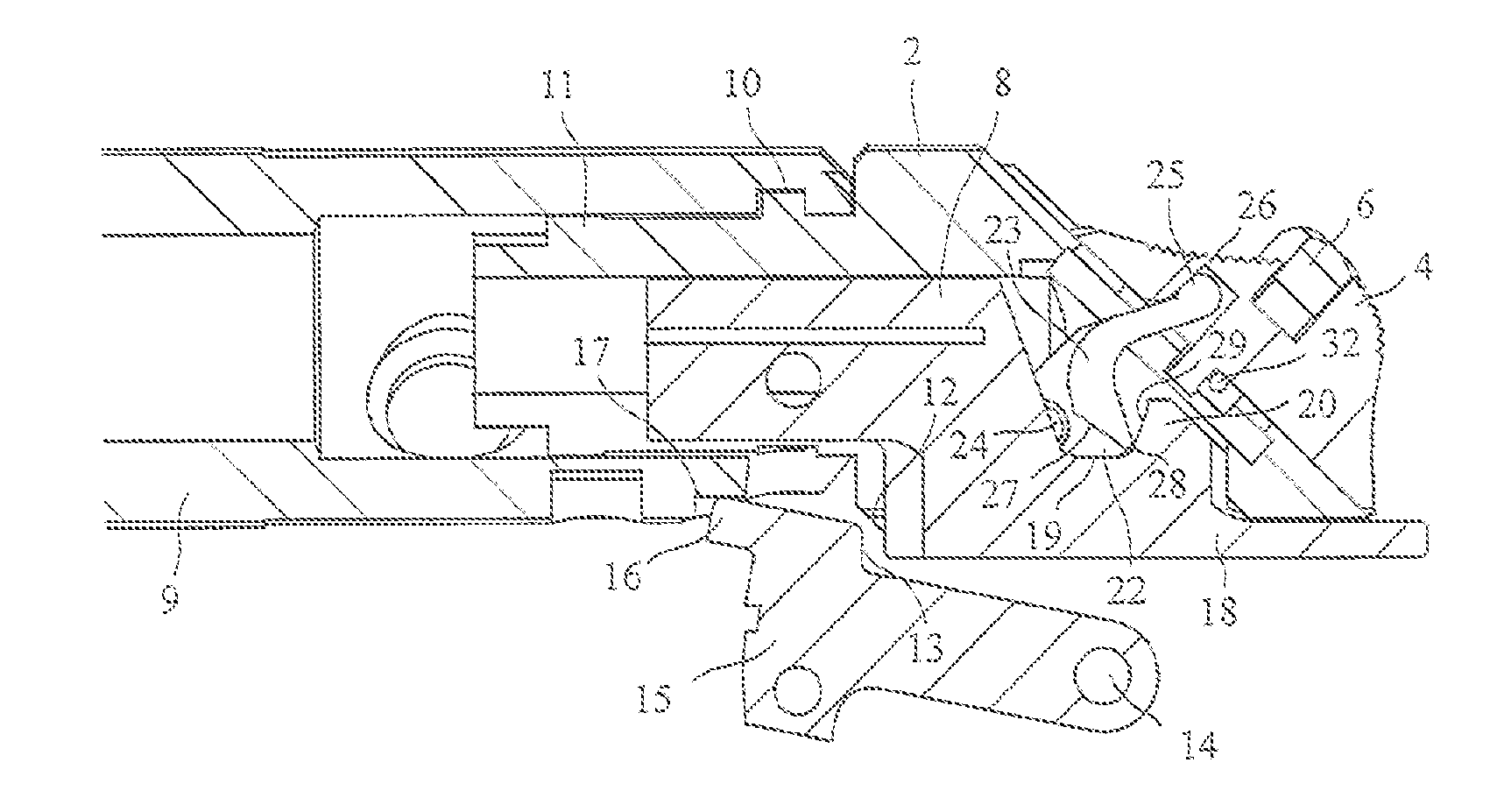
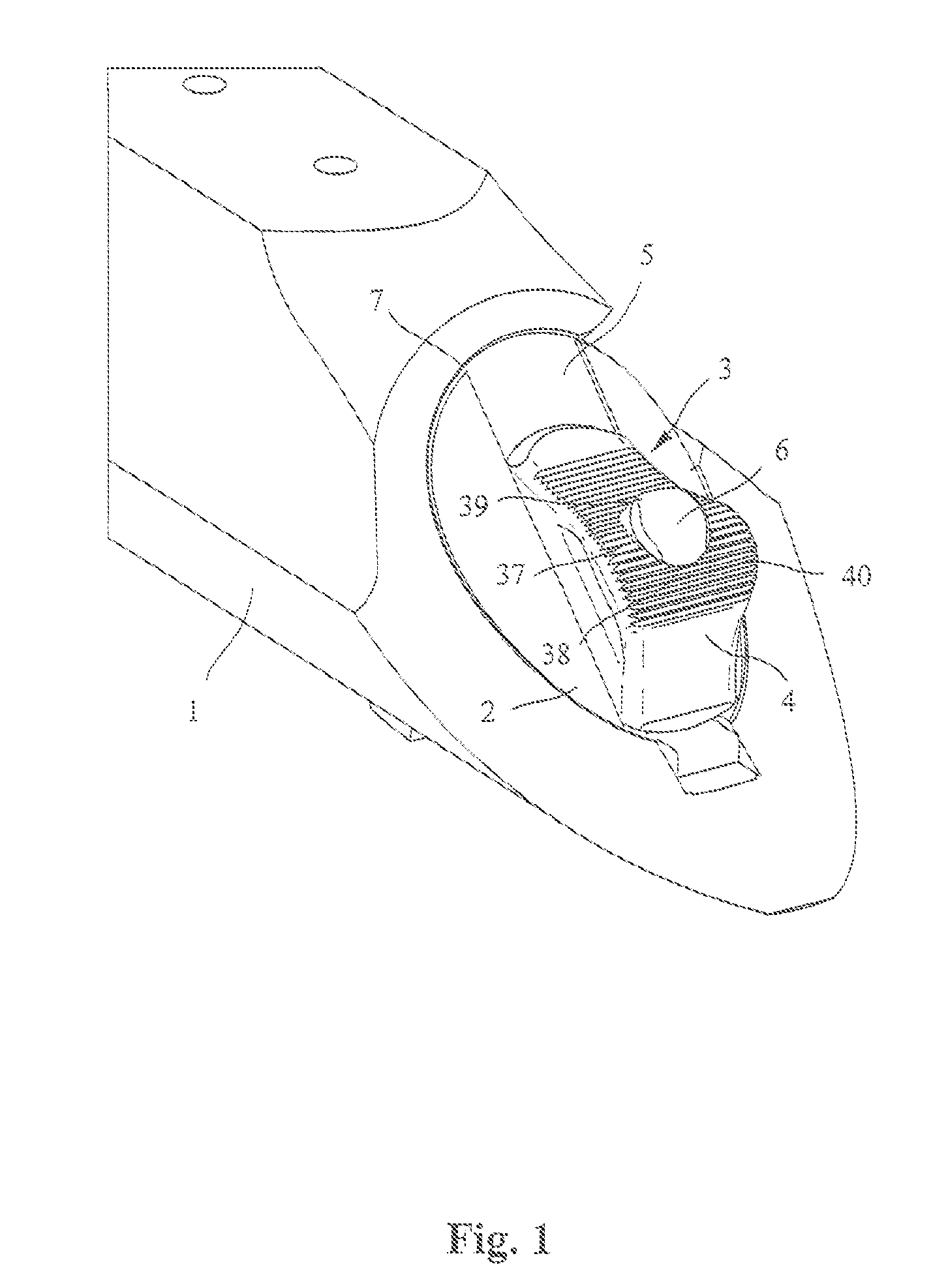
[0023]FIG. 1 shows the rear part of the system housing 1 of a repeating rifle with a so-called lock 2 and a safety 3 integrated into the lock 2 in a perspective view from the rear. The safety 3 contains a slider 4 that is displaceably guided inside a groove 5 on an inclined rear side of the lock 2 between a lower safety position and an upper unsecured position and is detachably held in the safety and unsecured positions by means of a securing element 6 configured as a pushbutton. The lock 2 arranged in a rear opening 7 of the system housing 1 is used in a conventionally known manner to guide a firing pin nut 8 shown in FIG. 2 that is guided displaceably in the longitudinal direction inside the lock 2.

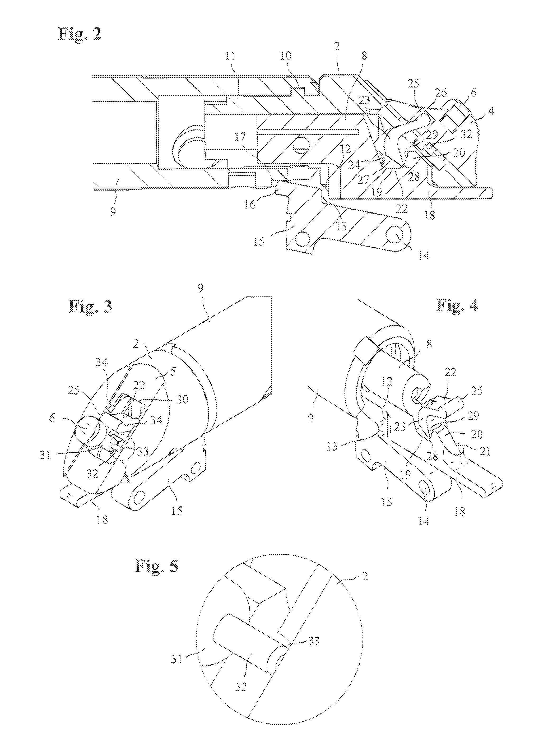
[0024]As is seen from FIG. 2, a hollow cylindrical chamber 9 is axially secured at its rear end via radial locking elements 10 in the manner of a bayonet fastener and is rotatably connected to a front part 11 of the lock. The firing pin nut 8, fixed in the known manner to the rear end o...


PUM


Abstract

The invention relates to a safety for a repeating rifle, with a safety slider (4) arranged displaceably between a safety position and an unsecured position on a lock (2), and a locking element associated with the safety slider (4) for blocking or releasing a firing pin nut (8) displaceably arranged in the lock (2). The locking element according to the invention is constructed as a safety lever (22), rotatable about a transverse pin (24), with a control part (23) engaging with a control groove (19) on the firing pin nut (8).

Description

FIELD OF THE INVENTION[0001]The invention relates to a safety for a repeating rifle.BACKGROUND OF THE INVENTION[0002]Such a safety is known from DE PS 1 235 187. Therein, a safety slider displaceable between a safety position and an unsecured position is mounted on a so-called lock. A locking element for blocking or releasing a firing pin nut movably guided in the lock is assigned to a safety slider serving as an actuation element. In this known safety, the locking element is configured as a spherical or roller-shaped rolling element for engagement in a keyway of the firing pin nut. Large operating forces are necessary, however, because the transmission ratio in this case is low and the friction of the cooperating parts is relatively high. Lifting the firing spring nut off of the sear arm against the force of the firing pin spring is associated with a large exertion of force.SUMMARY OF THE INVENTION[0003]An object of the invention is to create a safety of the type mentioned above th...

Claims


Application Information

Patent Timeline
IPC IPC(8): F41A17/70
CPCF41A17/80F41A17/70
Inventor OSTANIN, ALEXANDER
Owner BLASER FINANZHLDG
Why Eureka
Try Eureka