Ink jet recording apparatus

a recording apparatus and jet technology, applied in printing and other directions, can solve the problems of increasing the weight of the carriage, increasing the cost, and rapid decrease of pressure, and achieve the effects of preventing plastic deformation, reducing the cost, and reducing the cos

Inactive Publication Date: 2013-05-28
SEIKO I INFOTECH
View PDF15 Cites 0 Cited by
  • Summary
  • Abstract
  • Description
  • Claims
  • Application Information

AI Technical Summary

Benefits of technology

[0006]In order to solve the above-mentioned problem, the present invention disposes expansion means at a position of an ink container of a sub tank, which is apt to cause a plastic deformation, to thereby prevent the plastic deformation. A reinforcing material that has higher resilience than the material of the ink container of the sub tank is fixed. Alternatively, an external force is applied to the part that is apt to cause the plastic deformation by the expansion means in the deformation direction, to thereby prevent the plastic deformation of the ink container of the sub tank. As the reinforcing material, it is possible to use a resin sheet, a resin or metal plate, or the like. The reinforcing material may be fixed to the ink container by an adhesive or by welding. By fixing the reinforcing material to the ink container of the sub tank, it is possible to control the deformation due to expansion or compression of the ink container when ink flows in or out. Alternatively, a spring may be used as the external force.
[0007]According to the present invention, a change of internal pressure due to a plastic deformation of the ink container of the sub tank is prevented so that the internal pressure of the sub tank can be maintained to be constant. Thus, a fluctuation of pressure among individual ink containers is suppressed. Ink discharge from the ink jet head is stabilized and a discharge failure can be prevented, so that deterioration of print image quality can be prevented.

Problems solved by technology

However, in the conventional technique, it is necessary to provide pressure reducing pumps that are driven independently to the individual sub tanks.
In addition, the ink jet head, the sub tank, the pressure reducing pump, the pressure sensor, and the like are mounted on a carriage, resulting in an increase of weight of the carriage.
The increase of the number of components and the upsizing of the drive motor cause an increase of cost.
Further, because of contact between ink and air, dissolving of air containing oxygen and nitrogen in the ink occurs, which causes a rapid decrease of pressure accompanying air bubbles when an abrupt flow of ink occurs during a printing operation or a cleaning operation.
The air bubbles generate pressure relaxation effect of the ink jet heads and cause ink discharge failure.
However, as the sheets become harder, a change of pressure increases due to a volume change of the sheets.
Thus, it becomes difficult to generate an appropriate back pressure with respect to the ink jet heads.
However, as the material becomes softer, the ink container 2 is apt to change its volume and has little change of pressure while having poor ability to maintain the shape.
In addition, there is another problem that a fluctuation of pressure among individual ink containers 2 of the sub tank is large.

Method used


Image

  • Ink jet recording apparatus
  • Ink jet recording apparatus
  • Ink jet recording apparatus

Examples


Embodiment Construction

[0015]Embodiments of the present invention are described with reference to the attached drawings.

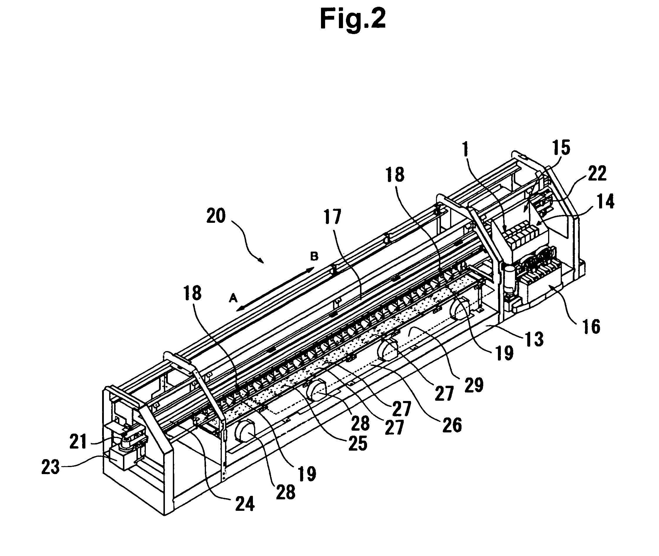
[0016]First, a recording apparatus in its entirety is described with reference to FIG. 2. FIG. 2 is a perspective view illustrating structure of the recording apparatus according to an embodiment of the present invention. An ink jet recording apparatus 20 conveys a sheet-like or plate-like recording medium 29 as illustrated in FIG. 2 by a broken line and records images and characters corresponding to image data on a surface of the recording medium 29 by an ink jet method. The recording medium 29 is a sheet or the like made of paper, fabric, or a synthetic resin such as polyester or PVC.

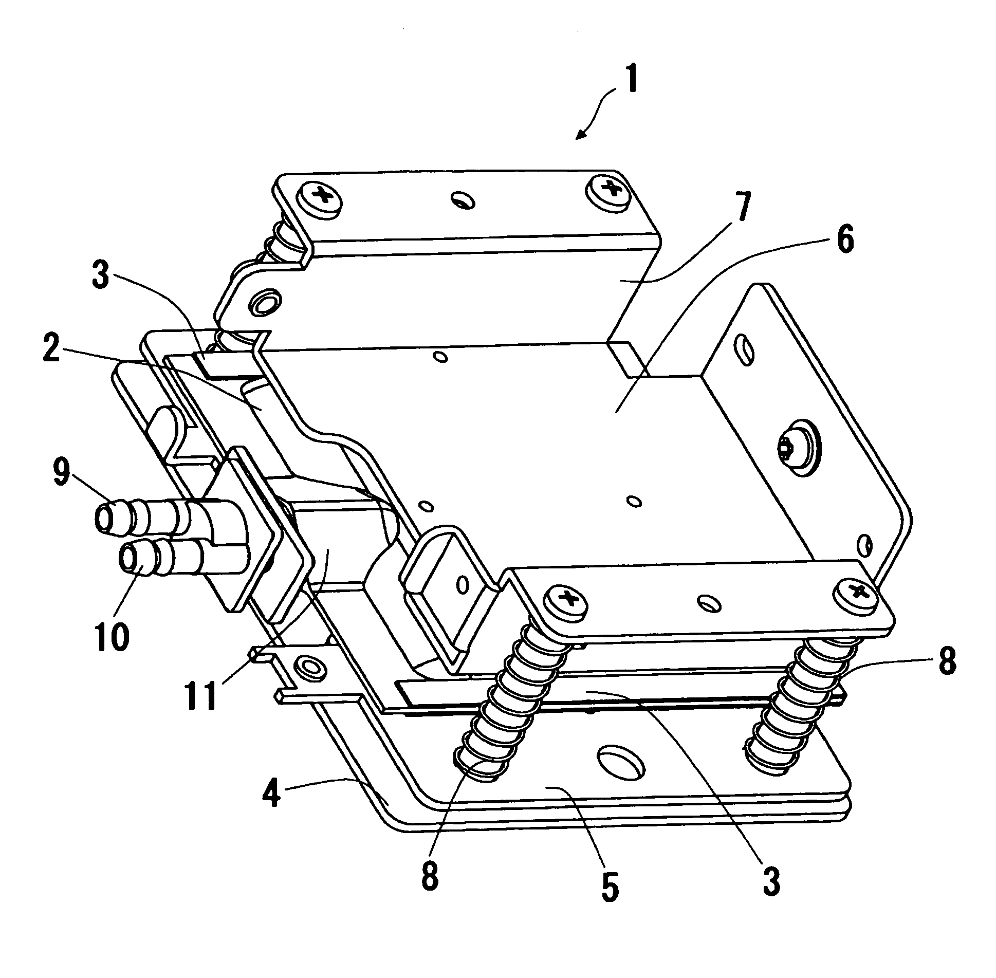
[0017]The ink jet recording apparatus 20 includes a conveyor roller 19 that is driven by a motor to rotate, and a pressure roller unit 18 which presses the conveyor roller 19. The recording medium 29 is sandwiched between the conveyor roller 19 and the pressure roller unit 18 and is conveyed by rotation of...


PUM


Abstract

An ink jet recording apparatus has a sub tank that supplies ink from an ink cartridge to an ink jet head carried by a reciprocating carriage. The sub tank has an ink container formed of two opposed resin films welded together around their peripheries, and resin sheet members are attached to the ink container over the weld portion for expanding the ink container and restoring it to its original shape after the ink container is deformed by ink flowing in or out of the ink container. The sheet members may be polyimide tape strips or the like that have higher resilience than the material of the ink container and prevent plastic deformation of the ink container due to expansion and compression thereof as ink flows in and out of the ink container.

Description

BACKGROUND OF THE INVENTION[0001]The present invention relates to a recording apparatus, and more particularly, to an ink jet recording apparatus.[0002]Conventionally, as described in Japanese Patent Application Laid-open No. 2005-34999, there is disclosed a system which maintains a constant pressure by providing a pressure reducing pump and an atmosphere communication valve to a sub tank, sensing a pressure in the sub tank with a pressure sensor, and driving the pressure reducing pump or driving the atmosphere communication valve based on the pressure value. In addition, an ink jet printer has ink jet heads for individual ink colors, so that sub tanks are provided for individual colors.[0003]However, in the conventional technique, it is necessary to provide pressure reducing pumps that are driven independently to the individual sub tanks. Therefore, the number of components increase, and the system is upsized. In addition, the ink jet head, the sub tank, the pressure reducing pump,...

Claims


Application Information

Patent Timeline
Patent Type & Authority Patents(United States)
IPC IPC(8): B41J2/175
CPCB41J2/17509B41J2/17513B41J2/17556B41J2/17553B41J2002/17516
Inventor MIDORIKAWA, MASARU
Owner SEIKO I INFOTECH
Why Eureka
Try Eureka