
Aircraft nacelle that incorporates a device for reversing thrust

a technology of thrust reverser and nacelle, which is applied in the direction of machines/engines, climate sustainability, sustainable transportation, etc., can solve the problems of reducing the performance level of the pivoting door or cascade type thrust reverser, and reducing the performance level of the propulsion unit. , to achieve the effect of not affecting aerodynamic performance, simple design, and optimized acoustic treatmen

Active Publication Date: 2013-05-28
AIRBUS OPERATIONS (SAS)
View PDF6 Cites 1 Cited by
  • Summary
  • Abstract
  • Description
  • Claims
  • Application Information

AI Technical Summary

Benefits of technology

The purpose of this invention is to create an aircraft nacelle with a reversed thrust device that is easy to design, effective in reducing noise, doesn't affect flying performance, and limits the amount of extra weight needed.

Problems solved by technology

Even if this approach simplifies the design of the device for reversing thrust, it imposes an additional constraint on the secondary duct, in particular a particular shape that tends to reduce the performance levels of the propulsion unit.
The pivoting-door-type or cascade-type thrust reversers are not satisfactory for the following reasons.
These configurations limit the inside surface of the nacelle that can comprise a coating for the acoustic treatment.
Actually, the connecting zones between the stationary parts and the moving parts, the zones at which the joints of the pivoting elements (doors or flaps) are provided, cannot comprise a coating for the acoustic treatment.
These configurations also produce aerodynamic losses in flows that flow into the secondary duct due to the numerous connections between the stationary parts and the moving parts and numerous obstacles that are present in the flow, such as the connecting rods for the flaps of the cascade reversers.
These configurations also produce adjustment difficulties between the stationary parts and the moving parts, in particular those that are used to deflect at least a portion of the flow because the deformation of said moving parts varies based on their position.

Method used


Image

  • Aircraft nacelle that incorporates a device for reversing thrust
  • Aircraft nacelle that incorporates a device for reversing thrust
  • Aircraft nacelle that incorporates a device for reversing thrust

Examples


Embodiment Construction

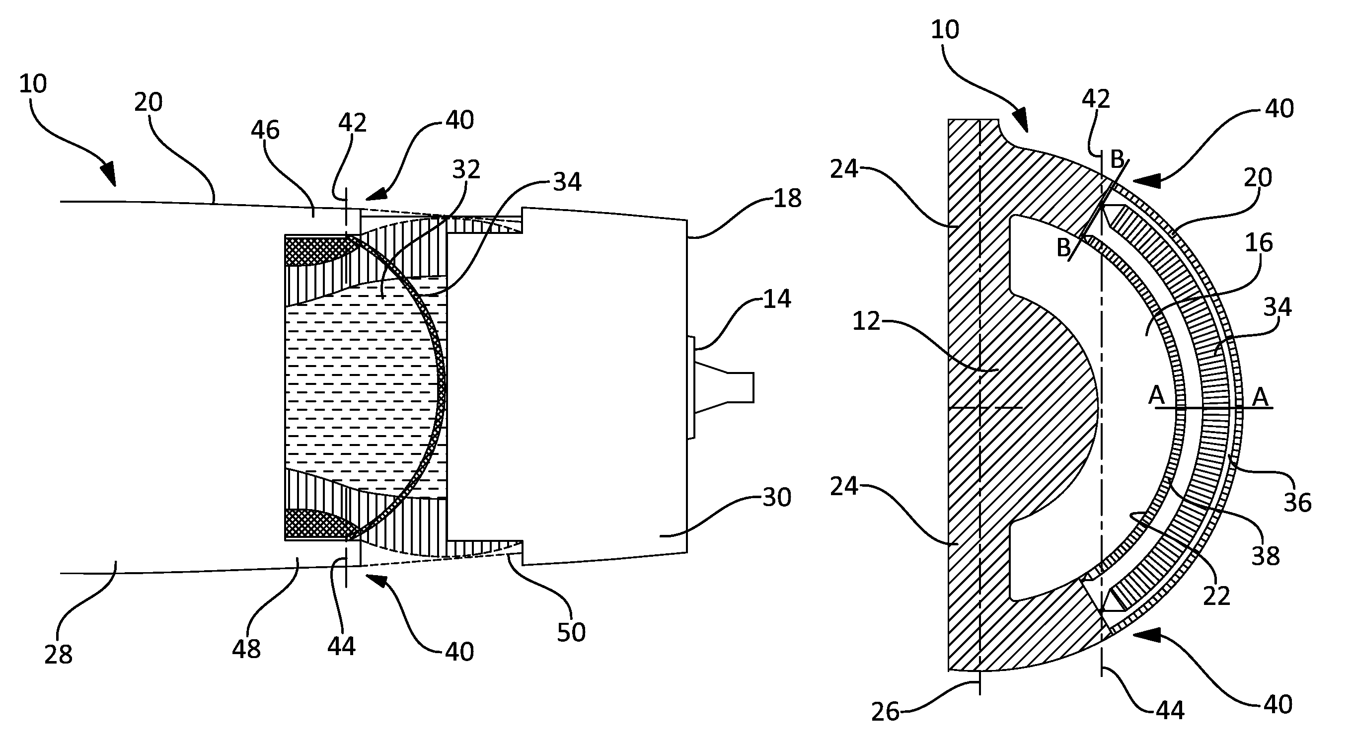
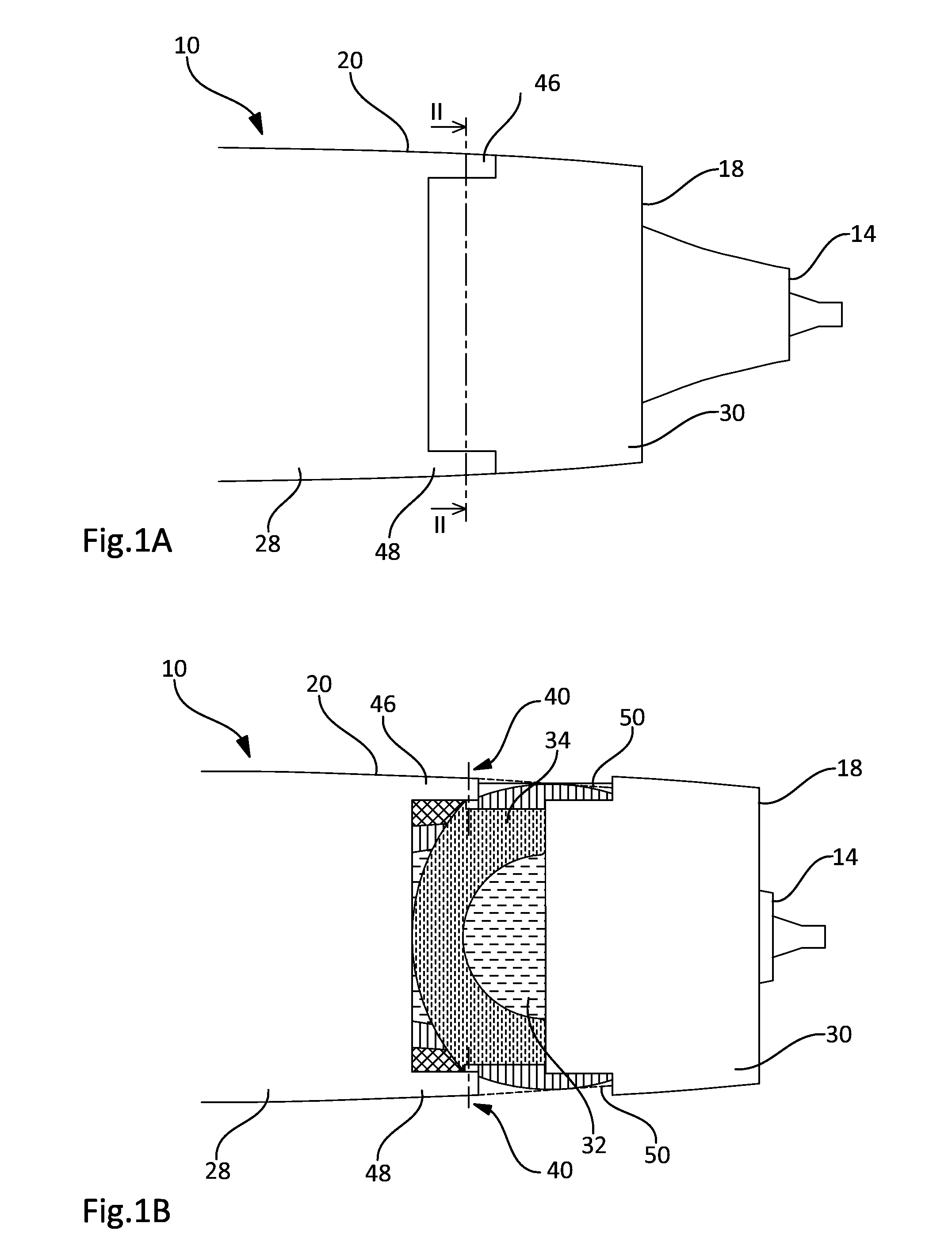
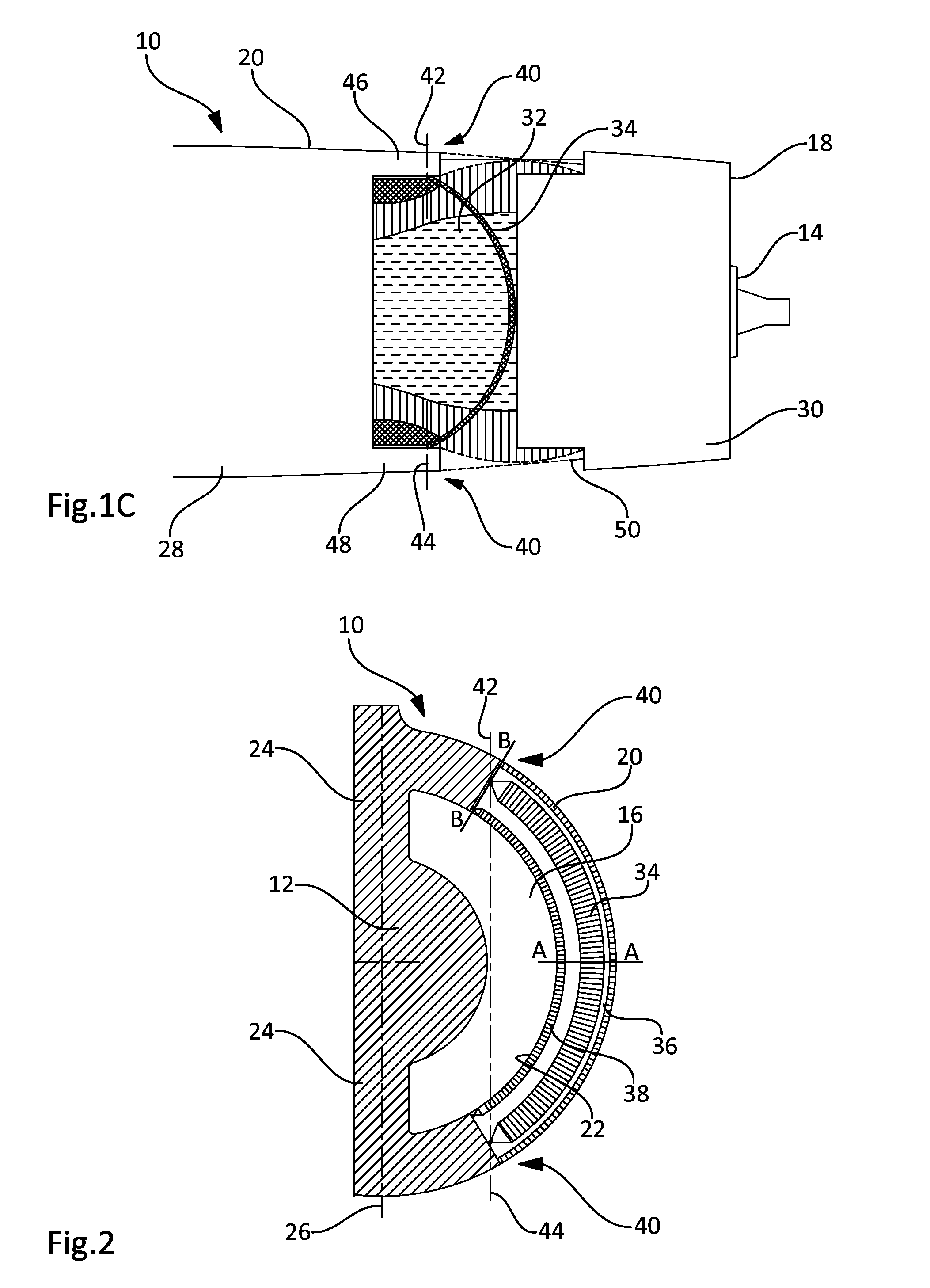
[0027]In the different figures, an aircraft nacelle is shown at 10 in which a power plant, shown diagrammatically at 12, can be arranged.

[0028]At the front, the nacelle 10 comprises an air intake that is divided into a primary duct that moves through the power plant and empties out via a primary exhaust 14 at the rear of the nacelle and into a secondary duct 16 that is provided at the rear of a fan that empties out via a secondary exhaust 18. Thus, the thrust of the propulsion unit that is formed by the nacelle and the power plant originates in particular from the ejection of fluid flow leaving the primary and secondary exhausts 14 and 18.

[0029]The nacelle comprises a first wall whose outside surface 20 is in contact with the fluid flows that flow outside of the nacelle and a second wall whose inside surface 22 delimits the secondary duct 16.

[0030]Two junctions 24 are generally arranged in the secondary duct 16 and form partitions arranged in a vertical plane, in angular positions r...


PUM


Abstract

An aircraft nacelle in which a power plant is arranged delimits a duct for a flow which assists the thrust. The nacelle includes a device for reducing, canceling, or reversing the thrust that includes at least one flap that can have an active position in which it deflects—in the direction of a radial opening—at least a portion of the flow and an at-rest position in which the flap does not interfere with the flow, whereby the wall of the nacelle delimiting the duct includes at least one moving part that can occupy a first position in which it is interposed between the flow to be deflected and the flap and another position in which it releases the flap so as to allow the flap to change position and to move from the at-rest position to the active position.

Description

BACKGROUND OF THE INVENTION[0001]1. Field of the Invention[0002]This invention relates to an aircraft nacelle and more particularly to a device that is provided on an aircraft nacelle to reduce, cancel or reverse thrust that is produced by a propulsion unit.[0003]2. Description of the Related Art[0004]An aircraft propulsion unit comprises an engine with, on the one hand, a fan that comprises a rotor that is equipped with blades and a stator that is equipped with paddles, and, on the other hand, a primary duct in which compressor stages, a combustion chamber, and turbine stages are arranged in the direction of the air flow. The engine is arranged in a nacelle that comprises an air intake upstream from the fan and a secondary duct downstream from the stator of the fan.[0005]In general, the nacelle consists of two junctions that are arranged in the secondary duct and along angular positions that are respectively greater than 12 o'clock and less than 6 o'clock. These two junctions const...

Claims


Application Information

Patent Timeline
Patent Type & Authority Patents(United States)
IPC IPC(8): F02K1/72
CPCF02K1/72Y02T50/671Y02T50/60
Inventor BULIN, GUILLAUMEOBERLE, PATRICK
Owner AIRBUS OPERATIONS (SAS)
Learn More