Brake control apparatus and control method for the brake control apparatus
a technology of brake control apparatus and control method, which is applied in the direction of braking system, instruments, analogue processes for specific applications, etc., can solve problems such as malfunctions in the first pressure sensor, and achieve the effect of suppressing the occurrence of malfunctions
- Summary
- Abstract
- Description
- Claims
- Application Information
AI Technical Summary
Benefits of technology
Problems solved by technology
Method used
Image
Examples
first embodiment
of the Invention
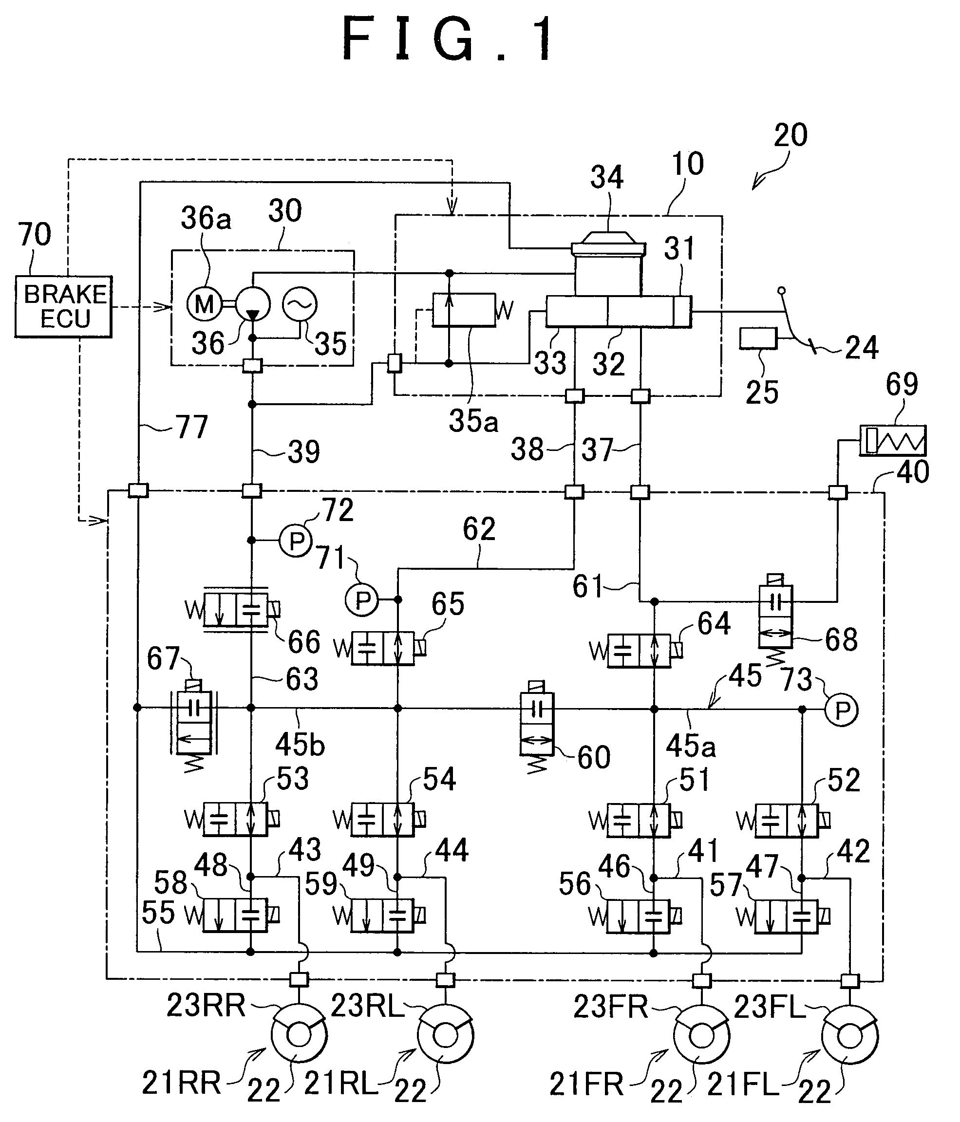
[0033]FIG. 1 is a system diagram showing a brake control apparatus 20 according to a first embodiment of the invention. The brake control apparatus 20 shown in FIG. 1 forms an electronically-controlled brake system for a vehicle, and controls braking forces that are applied to four wheels of a vehicle. The brake control apparatus 20 according to the first embodiment of the invention is mounted on, for example, a hybrid vehicle provided with an electric motor and an internal combustion engine that serve as drive power sources. In a hybrid vehicle, braking force may be applied to the vehicle through a regenerative braking operation in which kinetic energy of the vehicle is converted into electric energy and stored or a hydraulic pressure braking operation executed by the brake control apparatus 20. In the vehicle in the first embodiment of the invention, it is also possible to execute a cooperative braking control to generate desired braking force through combined exec...
second embodiment
of the Invention
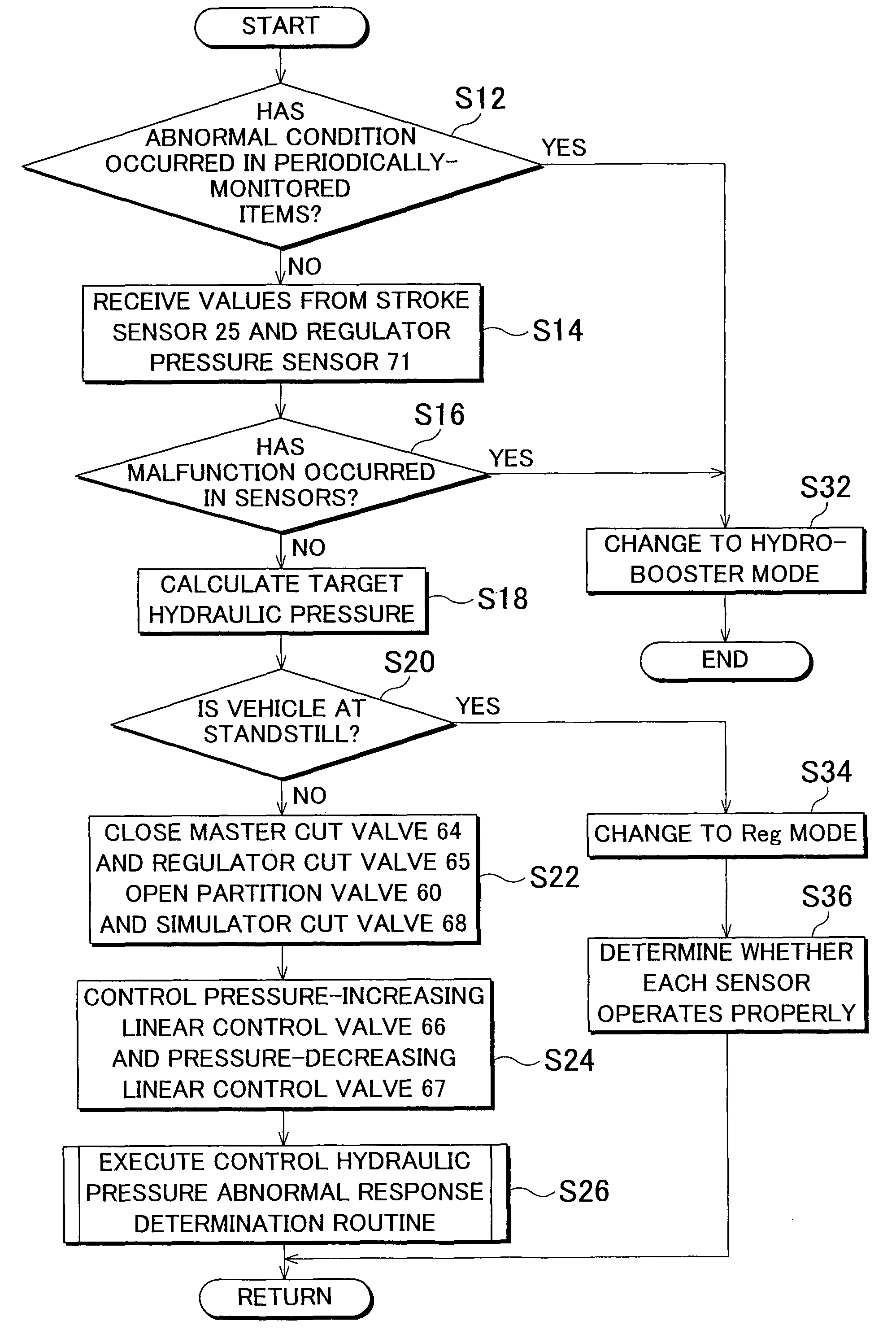
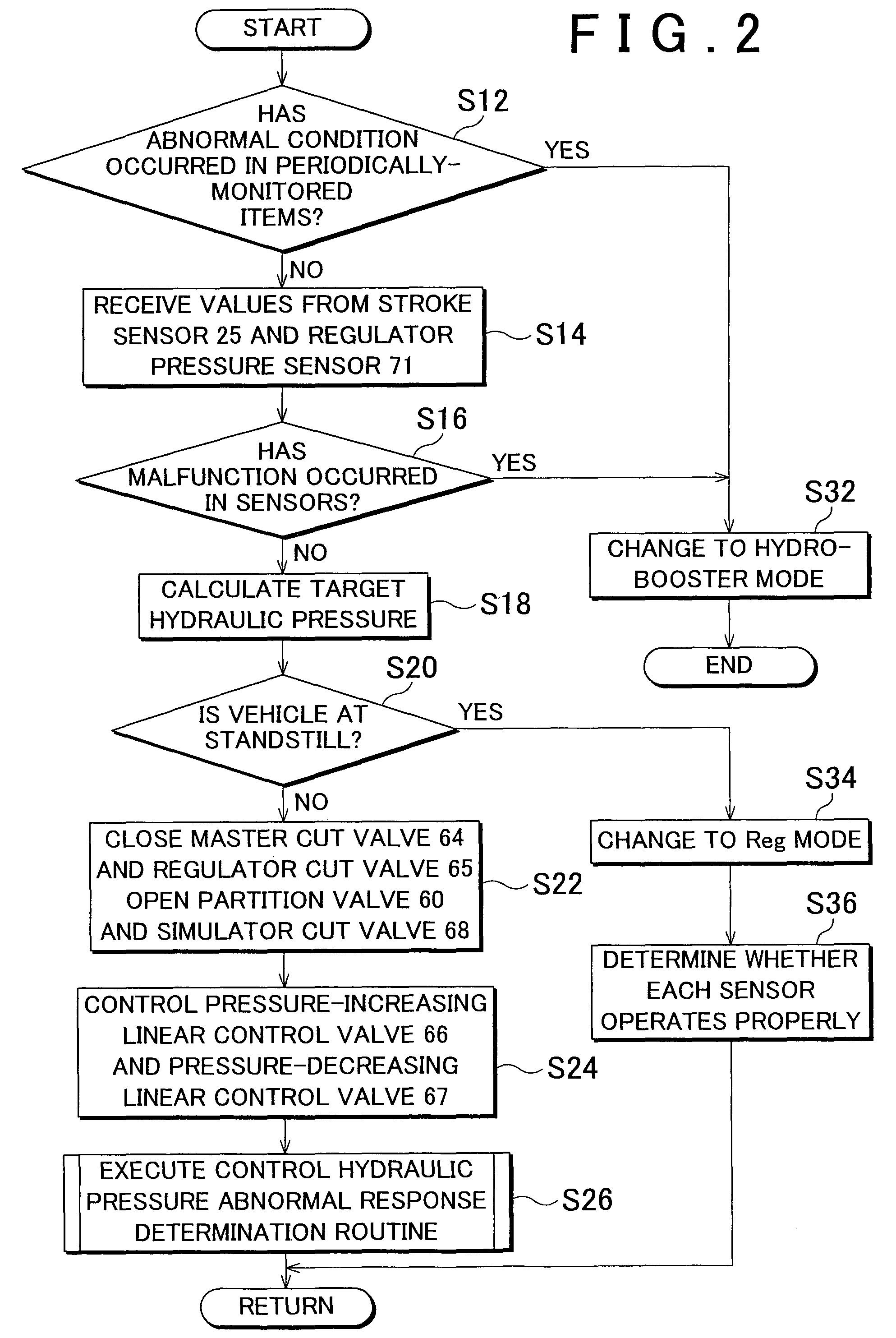
[0114]In a brake control apparatus 20 according to a second embodiment of the invention, if the pressure, which is detected by the control pressure sensor 73 while the partition valve 60 is closed, is equal to or higher than the predetermined value, the partition valve 60 and the pressure-decreasing linear control valve 67 are opened to suppress an increase in the pressure in the first passage 45a to which the control pressure sensor 73 is connected. FIG. 8 is a flowchart describing a control routine for protecting the control pressure sensor when the pressure is increased in the hydro-booster mode according to the second embodiment of the invention. Mainly, the features that differ from those in the first embodiment of the invention will be described below, and description concerning the features that are common to the first embodiment and the second embodiment of the invention will not be provided below.
[0115]The brake ECU 70 receives the detection value Pfr from t...
third embodiment
of the Invention
[0120]In a brake control apparatus 20 according to a third embodiment of the invention, if the pressure that is detected by the control pressure sensor 73 while the partition valve 60 is closed is equal to or higher than a predetermined value, the ABS pressure-decreasing valve 56 is opened to suppress an increase in the pressure in the first passage 45a to which the control pressure sensor 73 is connected. FIG. 9 is a flowchart describing a control routine for protecting the control pressure sensor when the pressure is increased in the hydro-booster mode according to the third embodiment of the invention. Mainly, the features that differ from those in the first and second embodiments of the invention will be described below, and description concerning the features that are common to the third embodiment and the first and second embodiments will not be provided below.
[0121]While the braking operation is performed in the hydro-booster mode, the brake ECU 70 receives th...
PUM
 Abstract
Description
Claims
Application Information
 - R&D
- Intellectual Property
- Life Sciences
- Materials
- Tech Scout
- Unparalleled Data Quality
- Higher Quality Content
- 60% Fewer Hallucinations
Browse by: Latest US Patents, China's latest patents, Technical Efficacy Thesaurus, Application Domain, Technology Topic, Popular Technical Reports.
© 2025 PatSnap. All rights reserved.Legal|Privacy policy|Modern Slavery Act Transparency Statement|Sitemap|About US| Contact US: help@patsnap.com


