Eureka AIR delivers breakthrough ideas for toughest innovation challenges, trusted by R&D personnel around the world.

Backscatter energy analysis for classification of materials based on positional non-commutativity

a positional non-commutativity and backscatter energy technology, applied in the field of material classification systems and methods, can solve the problems of difficult to use the backscatter intensity, atomic number has proved elusive, and the reliable mechanism for using the energy resolution of x-ray backscatter properties of objects

Active Publication Date: 2013-05-14
AMERICAN SCI & ENG INC
View PDF10 Cites 35 Cited by
  • Summary
  • Abstract
  • Description
  • Claims
  • Application Information

AI Technical Summary

Problems solved by technology

However, because the backscatter intensity is a complicated function of the distance, position, and the shape and thickness of the object, as well as the amount of intervening clutter obscuring the object, it is difficult to use the backscatter intensity to further classify the organic material.
Consequently, a reliable mechanism for using energy resolution of x-ray backscatter properties of an object to classify the object by atomic number has proven elusive.
However, if this is to be accomplished using the techniques taught by Annis, the end-point energy of the lower energy must be very low (only about 30 keV or less), making the practical application of this technique problematic for a practical body scanner, because of the high attenuation of x-rays in this energy range by intervening clothing between the x-ray source and the inspected person's body.
Moreover, the teachings of Annis nowhere address the question of whether highly scattering objects, such as organic materials, lie in front of, or behind, a highly attenuating structural feature such as a sheet of high-Z material, such as a steel car body, for example.

Method used


Image

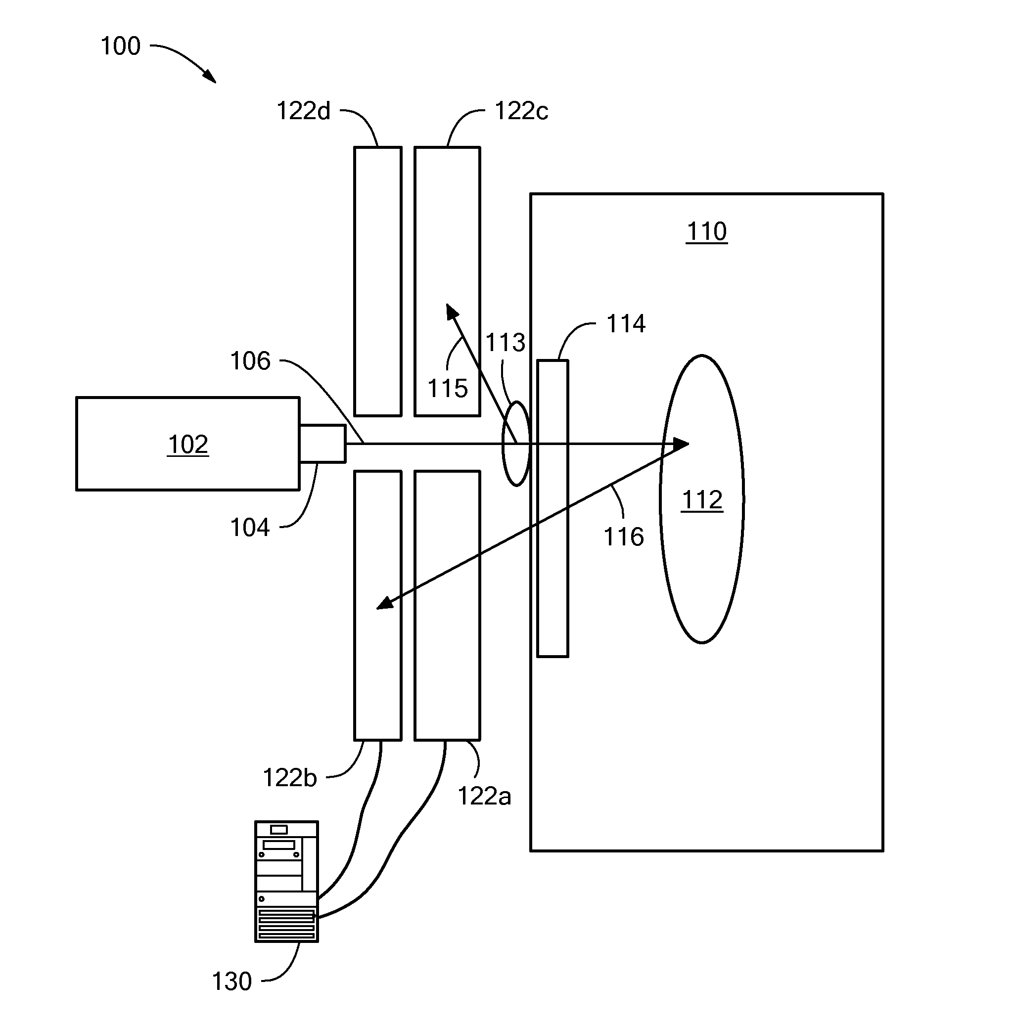
  • Backscatter energy analysis for classification of materials based on positional non-commutativity
  • Backscatter energy analysis for classification of materials based on positional non-commutativity
  • Backscatter energy analysis for classification of materials based on positional non-commutativity

Examples


Embodiment Construction

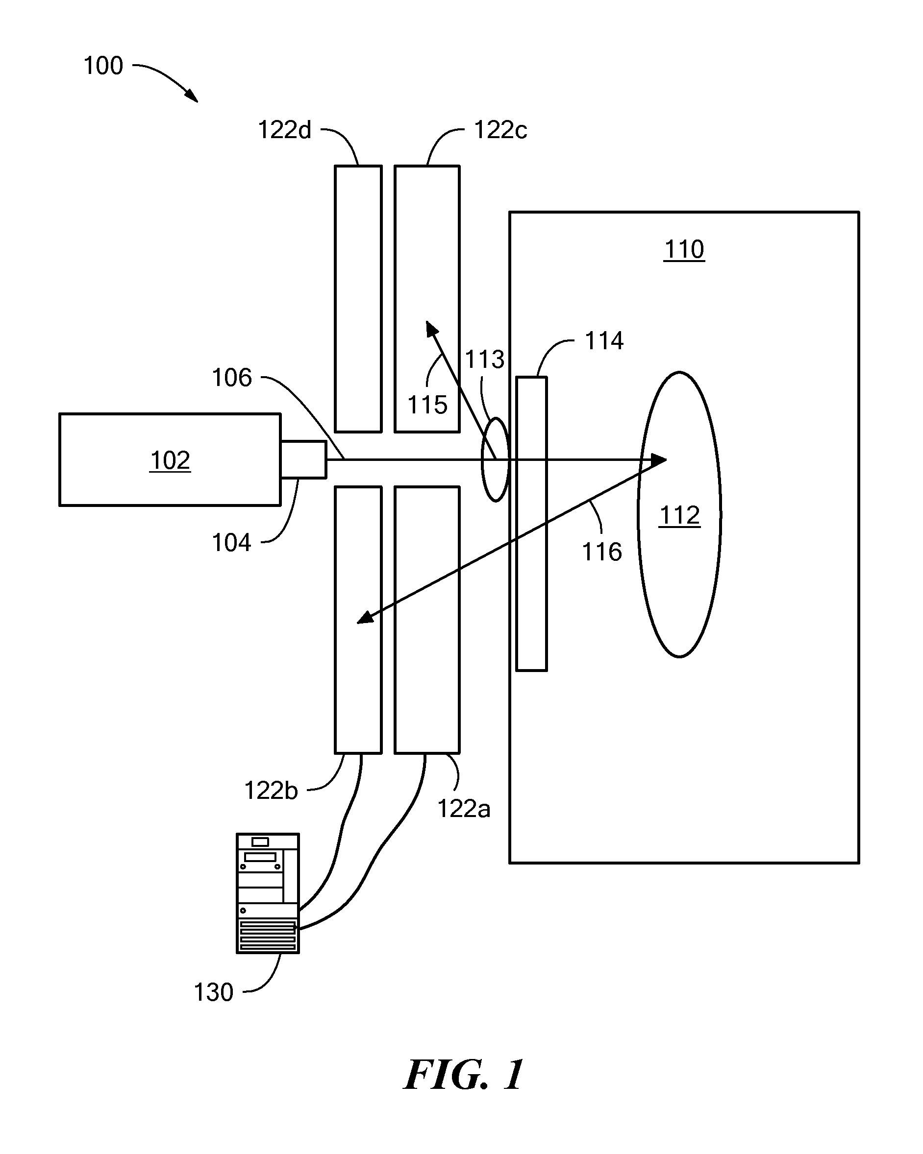
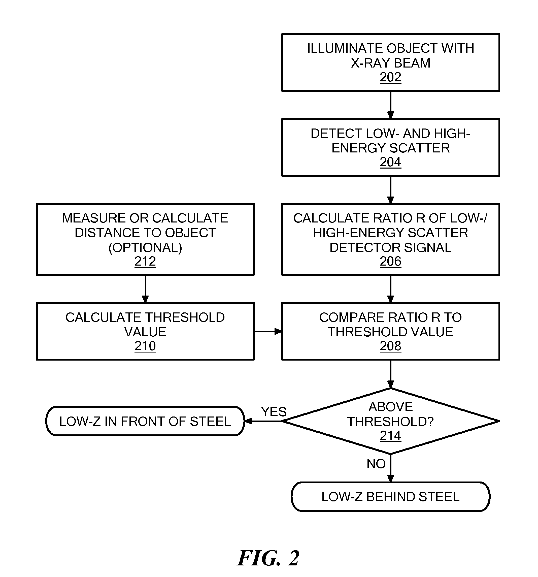
[0013]In accordance with various embodiments of the present invention, methods are provided for characterizing regions within an inspected object wherein a lower-Z scattering material and a higher-Z material may both lie along a common line of sight. The methods have steps of:[0014]a. scanning the inspected object with penetrating radiation emitted by a source characterized by an energy distribution;[0015]b. detecting penetrating radiation scattered by the inspected object in a manner generating a first detector signal that distinguishes between materials of higher and lower effective atomic number under a first set of conditions with respect to the energy distribution of the penetrating radiation;[0016]c. detecting penetrating radiation scattered by the inspected object in a manner generating a second detector signal that distinguishes between materials of higher and lower effective atomic number under a second set of conditions with respect to the energy distribution of the penetr...


PUM

PropertyMeasurementUnit
distanceaaaaaaaaaa
mean energyaaaaaaaaaa

Abstract

A system and methods for characterizing regions within, or on, an inspected object, wherein a lower-Z scattering material and a higher-Z material may both lie along a common line of sight. The inspected object is scanned with penetrating radiation characterized by an energy distribution, and penetrating radiation scattered by the inspected object is detected in a manner that generates two detector signals that distinguish between materials of higher and lower effective atomic number under distinct sets of conditions with respect to the energy distribution of the penetrating radiation. An image is generated, based on a function of the two detector signals, as is a differential image, so as to allow distinction of higher-Z and lower-Z materials.

Description

[0001]The present application claims the priority of U.S. Provisional Patent Application 61 / 440,491, filed Feb. 8, 2011, and incorporated herein by reference.TECHNICAL FIELD[0002]The present invention relates to systems and methods for classifying materials as to their effective atomic numbers based on detection of penetrating radiation scattered therefrom.BACKGROUND ART[0003]Backscatter x-ray inspection systems have been used for more than 25 years to detect organic materials concealed inside baggage, cargo containers, in vehicles, and on personnel. Because organic materials in bulk preferentially scatter x-rays (by Compton scattering) rather than absorb them, these materials appear as brighter objects in backscatter images. However, because the backscatter intensity is a complicated function of the distance, position, and the shape and thickness of the object, as well as the amount of intervening clutter obscuring the object, it is difficult to use the backscatter intensity to fur...

Claims


Application Information

Patent Timeline
Patent Type & Authority Patents(United States)
IPC IPC(8): G01N23/201
CPCG01N23/203G01V5/0025
Inventor ROTHSCHILD, PETERZHANG, MING
Owner AMERICAN SCI & ENG INC
Why Eureka
Eureka Blog
Learn More