
Communication apparatus, communication method and integrated circuit

a communication apparatus and integrated circuit technology, applied in the field of communication apparatus, communication method and integrated circuit, can solve the problems of not always improving the actual communication rate, requiring a wider dynamic range, and not easy to realize a power line communication apparatus capable of carrying out communication, etc., to achieve efficient communication and suppress the leakage of communication signals.

Active Publication Date: 2013-05-14
PANASONIC CORP
View PDF28 Cites 4 Cited by
  • Summary
  • Abstract
  • Description
  • Claims
  • Application Information

AI Technical Summary

Benefits of technology

The patent describes a communication device that can efficiently use a wide range of frequencies. The device can have multiple communication units that can work simultaneously or selectively. By synchronizing the first communication unit with the second, it can minimize signal interference from the other side. This advantage is especially useful when using separate communication units with two different devices. The device can be implemented using a single hardware device or separate hardware devices. Overall, the patent describes a technical solution for efficient communication across a wide range of frequencies.

Problems solved by technology

As for the transmission of the OFDM scheme, a communication speed (communication rate) in the broad frequency band is improved theoretically, but the communication rate is not always improved actually.
Accordingly, since a wide dynamic range is necessary for an AD converter or a DA converter, it is not easy to realize a power line communication apparatus capable of carrying out communication in a state where the low band and the high band is both used optimally.
When a FDM (Frequency Division Multiplex) is carried out using the low band and the high band, a perspective problem (which refers to a phenomenon that the level difference is considerable between the low band and the high band) of the low band and the high band occurs in addition to the restriction of the TDM, thereby requiring the wider dynamic range.
However, it is generally difficult to use the steep BPF.

Method used


Image

  • Communication apparatus, communication method and integrated circuit
  • Communication apparatus, communication method and integrated circuit
  • Communication apparatus, communication method and integrated circuit

Examples


Embodiment Construction

[0035]Hereinafter, an embodiment will be described with reference to the drawings.

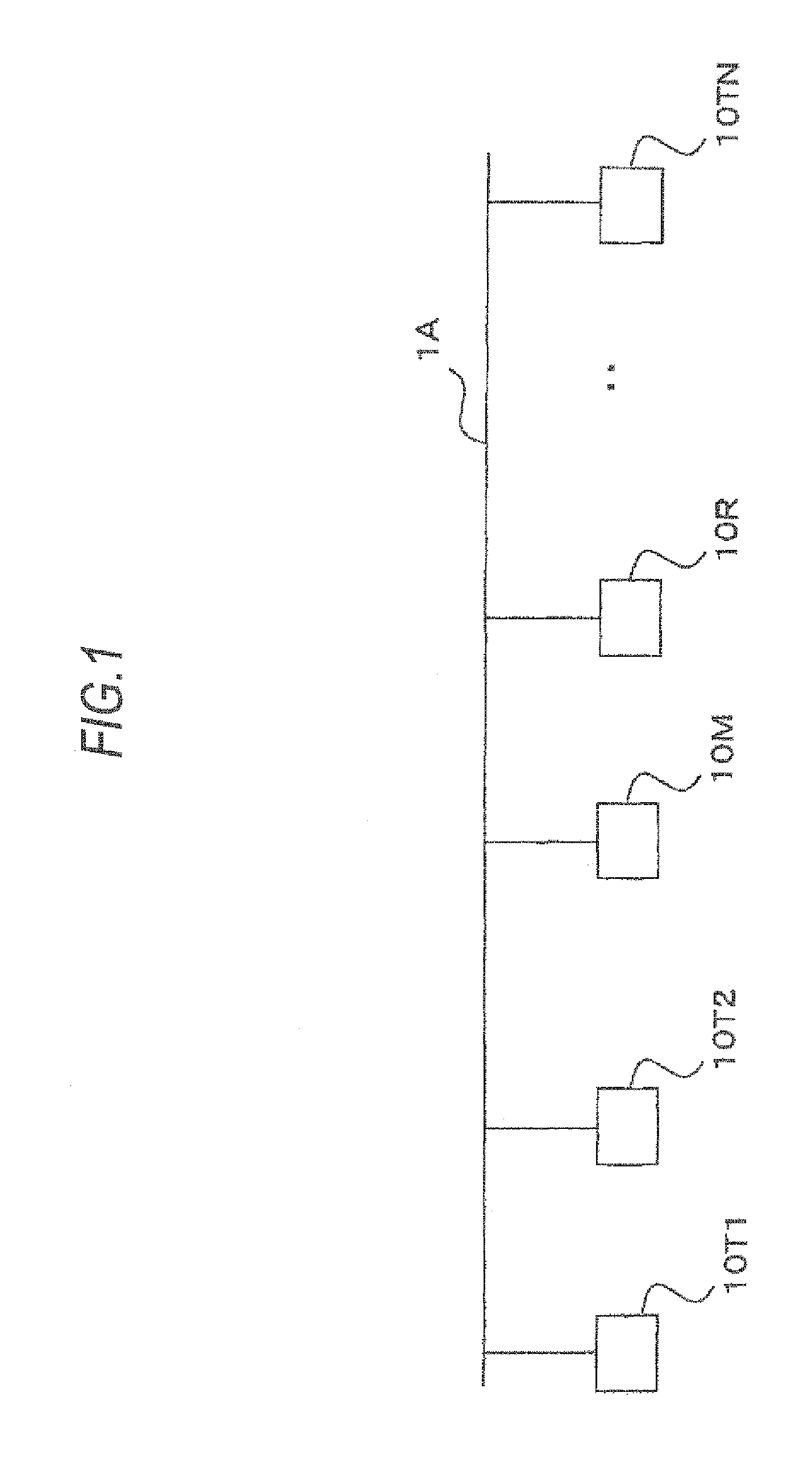
[0036]As illustrated in FIG. 1, a power line communication system includes a plurality of PLC (Power Line Communication) modems 10M, 10R 10T1, 10T2, . . . , and 10TN connected to a power line 1A. In FIG. 1, five PLC modems are illustrated, but any number of PLC modems is connected. The PLC modem 10M which serves as a master manages a connection state (link state) of other PLC modem 10T1, . . . , and 10TN which serve as slaves. In addition, the PLC modem 10R serves as a repeater which repeats communication between other PLC modems. However, the PLC modem which serves as the master and the PLC modem which serves as the repeater are not essential elements.

[0037]In the following description, the terms of the PLC modem 10M, 10R, 10T1, 10T2, . . . , and 10TN are used when the master, the repeater, and specific slaves are mentioned, and the term of PLC modem 10T is used when the stave is generally mentioned. ...


PUM


Abstract

A communication apparatus carries out multicarrier communication with another communication apparatus through a transmission channel. The communication apparatus includes a first communication unit which carries out communication using a subcarrier at a first frequency band; a second communication unit which carries out communication using a subcarrier at a second frequency band higher than the first frequency band; and a third communication unit which carries out communication by synchronizing the first communication unit with the second communication unit and concurrently using the first and second frequency bands.

Description

BACKGROUND[0001]1. Technical Field[0002]The present invention relates to a communication apparatus, a communication method, and an integrated circuit capable of carrying out communication using a plurality of subcarriers.[0003]2. Background Art[0004]A transmission scheme of using a plurality of subcarriers, such as an OFDM (Orthogonal Frequency Division Multiplexing) scheme has a big advantage of realizing high quality communication even over a transmission channel of a severe condition, and thus is used for wired communication such is as power line communication as well as wireless communication. A frequency band usable for the power line communication is generally in the range of 2 MHz to 30 MHz as in JP-A-2007-259176. The frequency bands usable for the power line communication are each assigned as a proper value of each nation according to the national law of each nation. However, it is considered that a broader frequency band containing a higher frequency is used.[0005]As for th...

Claims


Application Information

Patent Timeline
Patent Type & Authority Patents(United States)
IPC IPC(8): H04K1/10
CPCH04L5/06H04B2203/5408H04B2203/5445
Inventor KOGA, HISAOKODAMA, NOBUTAKA
Owner PANASONIC CORP
Learn More