
Heat spreader package

a heat spreader and heat dissipation device technology, applied in the field of electronic components, can solve problems such as inadvertent contact between the heat spreader and electrically conductive structures, and associated failure of the electronic component packag

Active Publication Date: 2013-05-14
AMKOR TECH SINGAPORE HLDG PTE LTD
View PDF32 Cites 9 Cited by
  • Summary
  • Abstract
  • Description
  • Claims
  • Application Information

AI Technical Summary

Benefits of technology

Prevents shorting between bond wires and the heat spreader while efficiently dissipating heat from the electronic component, ensuring the package's reliability and performance.

Problems solved by technology

As the dimensions of the electronic component package become extremely small, inadvertent contact between the heat spreader and electrically conductive structures, e.g., bond wires, of the electronic component package can occur.
This inadvertent contact with the heat spreader causes shorting and the associated failure of the electronic component package.

Method used


Image

  • Heat spreader package
  • Heat spreader package
  • Heat spreader package

Examples


Embodiment Construction

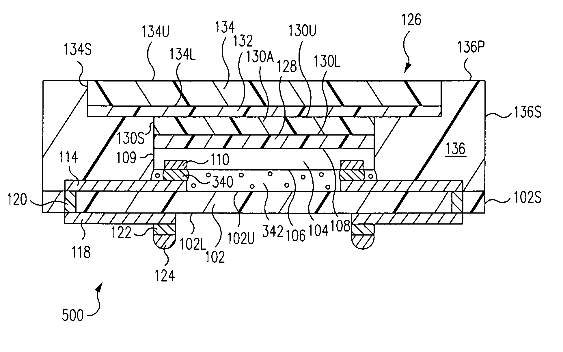
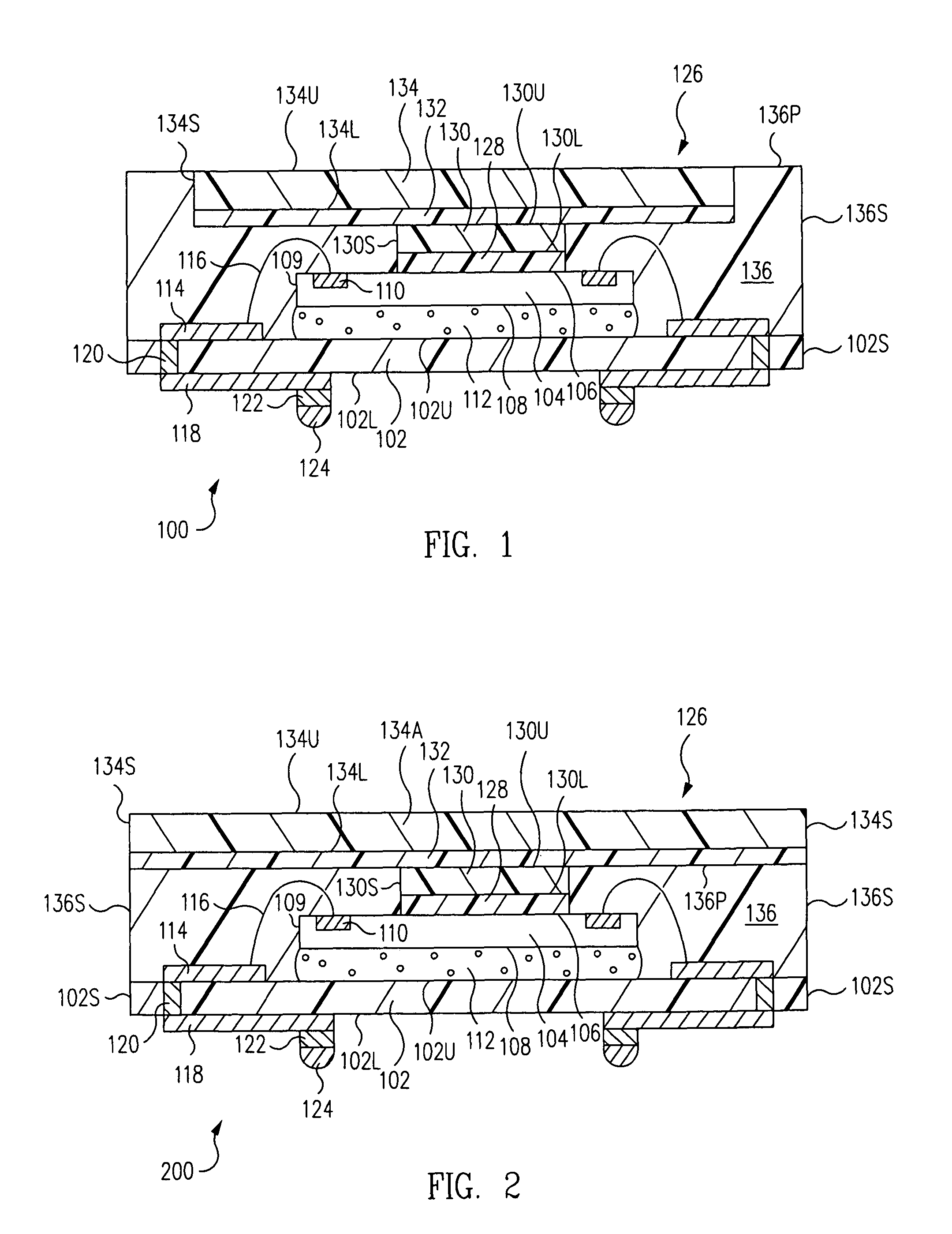
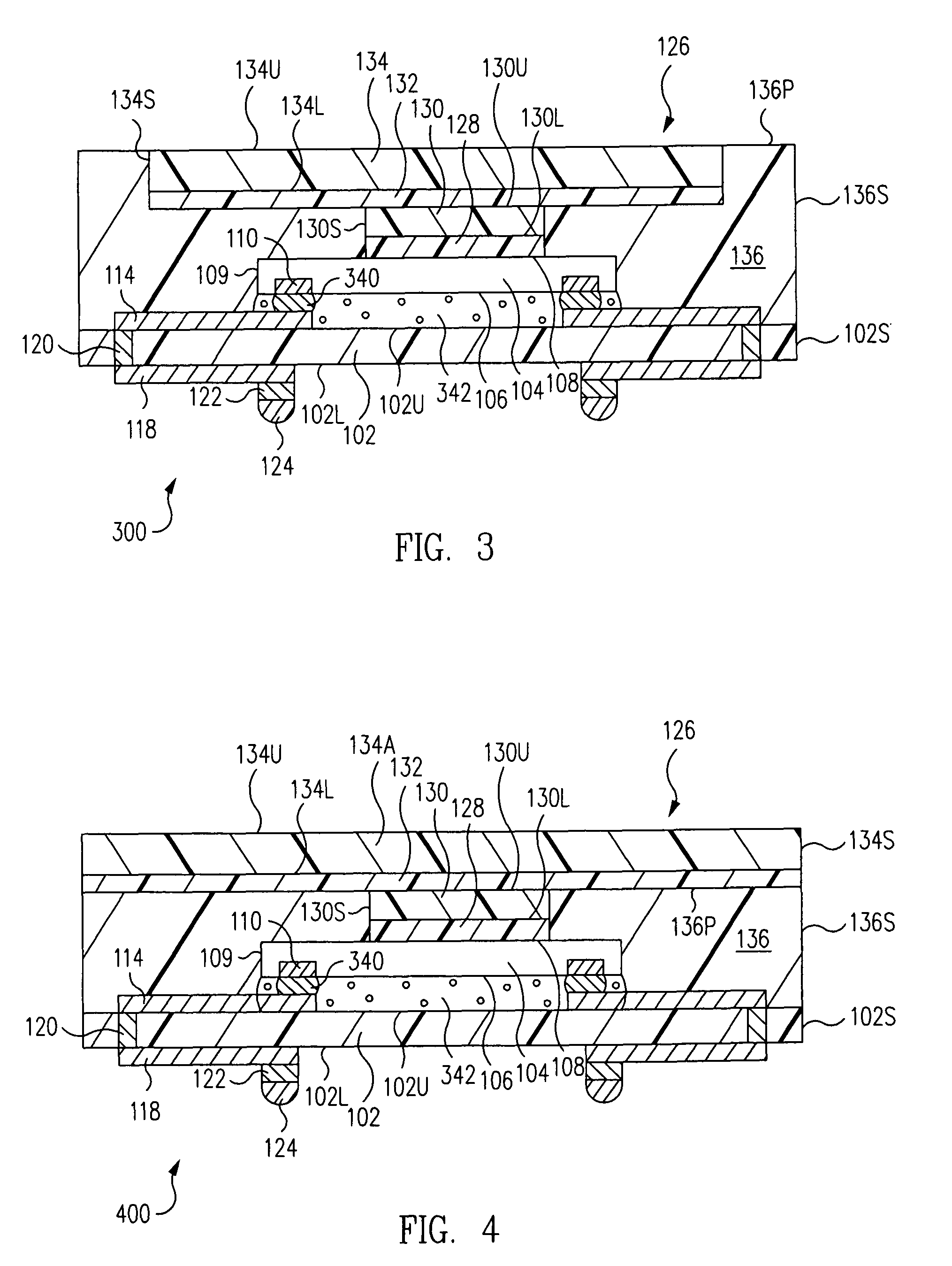
[0011]As an overview, referring to FIG. 1, a heat spreader package 100 includes a substrate 102 having an upper surface 102U, upper traces 114 on upper surface 102U of substrate 102, and an electronic component 104 having an inactive surface 108 mounted to upper surface 102U of substrate 102. Electronic component 104 further includes an active surface 106 having bond pads 110.

[0012]Bond wires 116 electrically connect bond pads 110 to upper traces 114. An inverted pyramid heat spreader 126 includes a lower heatsink 130, a lower heatsink adhesive 128 directly connecting lower heatsink 130 to active surface 106 of electronic component 104 inward of bond pads 110, an upper heatsink 134 having an absence of active circuitry, and an upper heatsink adhesive 132 directly connecting a lower surface 134L of upper heatsink 134 to lower heatsink 130. Upper heatsink adhesive 132 is a dielectric directly between bond wires 116 and upper heatsink 134 that prevents inadvertent shorting between bond...


PUM


Abstract

A heat spreader package includes a substrate having a first surface, first traces on the first surface of the substrate, and an electronic component having an inactive surface mounted to the first surface of the substrate. The electronic component further includes an active surface having bond pads. Bond wires electrically connect the bond pads to the first traces. An inverted pyramid heat spreader includes a first heatsink, a first heatsink adhesive directly connecting the first heatsink to the active surface of the electronic component inward of the bond pads, a second heatsink having an absence of active circuitry, and a second heatsink adhesive directly connecting a first surface of the second heatsink to the first heatsink. The second heatsink adhesive is a dielectric directly between the bond wires and the second heatsink that prevents inadvertent shorting between the bond wires and the second heatsink.

Description

RELATED APPLICATIONS[0001]This application is a continuation of Arcedera et al., U.S. patent application Ser. No. 12 / 702,505, filed on Feb. 9, 2010, entitled “HEAT SPREADER PACKAGE AND METHOD”, now U.S. Pat. No. 7,999,371, issued on Aug. 16, 2011, which is herein incorporated by reference in its entirety.BACKGROUND OF THE INVENTION[0002]1. Field of the Invention[0003]The present application relates to the field of electronics, and more particularly, to methods of forming electronic component packages and related structures.[0004]2. Description of the Related Art[0005]An electronic component package includes an electronic component. During operation, the electronic component generates heat. To prevent overheating of the electronic component, a heat spreader is included in the electronic component package. Heat generated by the electronic component is dissipated to the heat spreader thus avoiding overheating of the electronic component.[0006]Often, the heat spreader is made of an elec...

Claims


Application Information

Patent Timeline
Patent Type & Authority Patents(United States)
IPC IPC(8): H01L23/31
CPCH01L23/433H01L2224/48091H01L2224/48227H01L2224/73265H01L2924/00014H01L24/48H01L2224/16225H01L2224/32225H01L2224/73204H01L2924/00H01L2224/73253H01L2924/15311H01L2924/00012H01L24/73H01L2924/14H01L2924/181H01L2224/45099H01L2224/45015H01L2924/207
Inventor ARCEDERA, ADRIANKANUPARTHI, SASANKA LAXMI NARASIMHA
Owner AMKOR TECH SINGAPORE HLDG PTE LTD
Learn More