
Sub-circuit pattern recognition in integrated circuit design

a technology of integrated circuit design and sub-circuit pattern recognition, applied in the field of electronic devices, can solve the problems of increasing the computational complexity of the extraction scheme, and the inability to compare devices or components in a straightforward manner,

Active Publication Date: 2013-04-30
TEXAS INSTR INC
View PDF5 Cites 13 Cited by
  • Summary
  • Abstract
  • Description
  • Claims
  • Application Information

AI Technical Summary

Benefits of technology

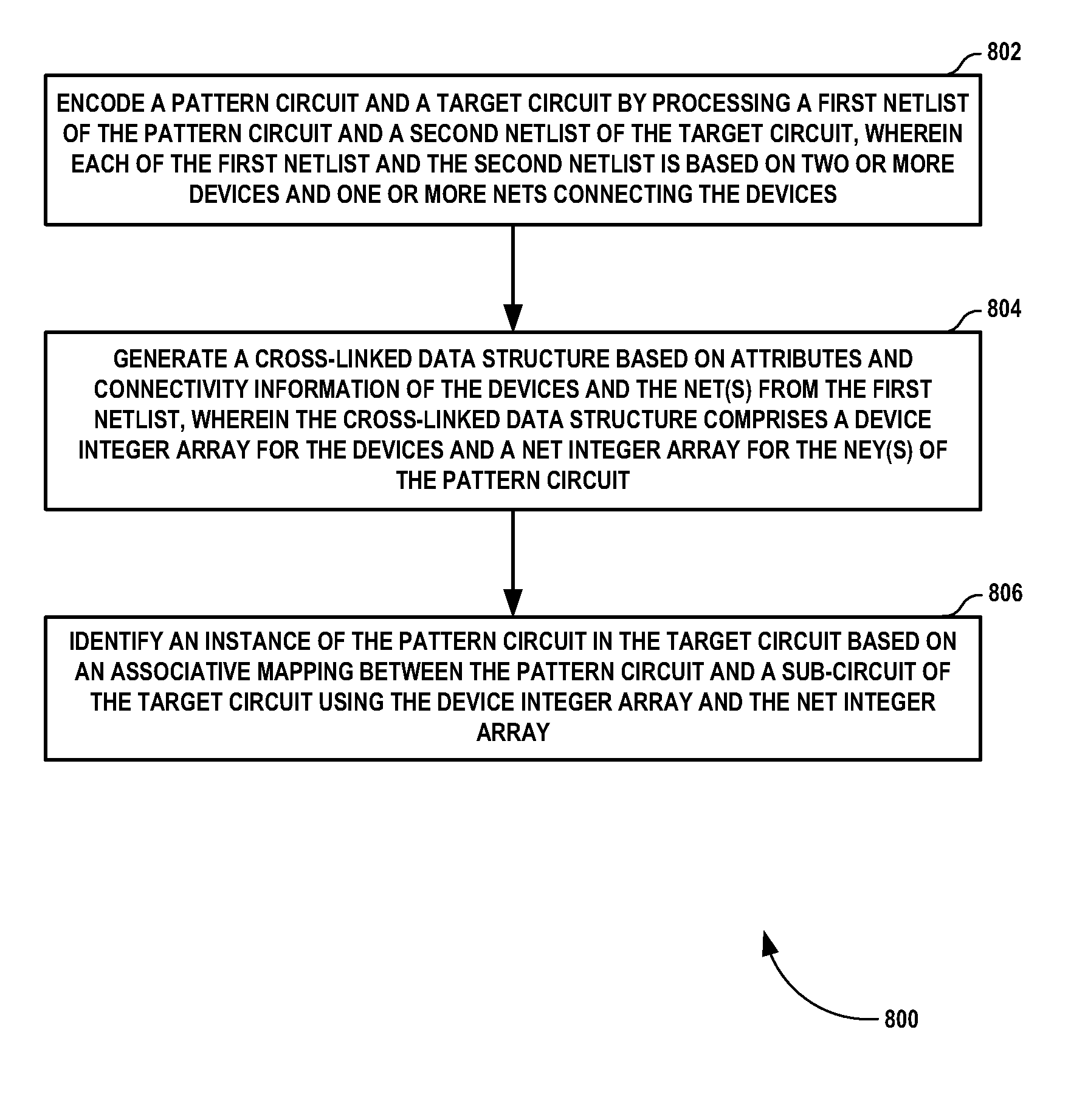
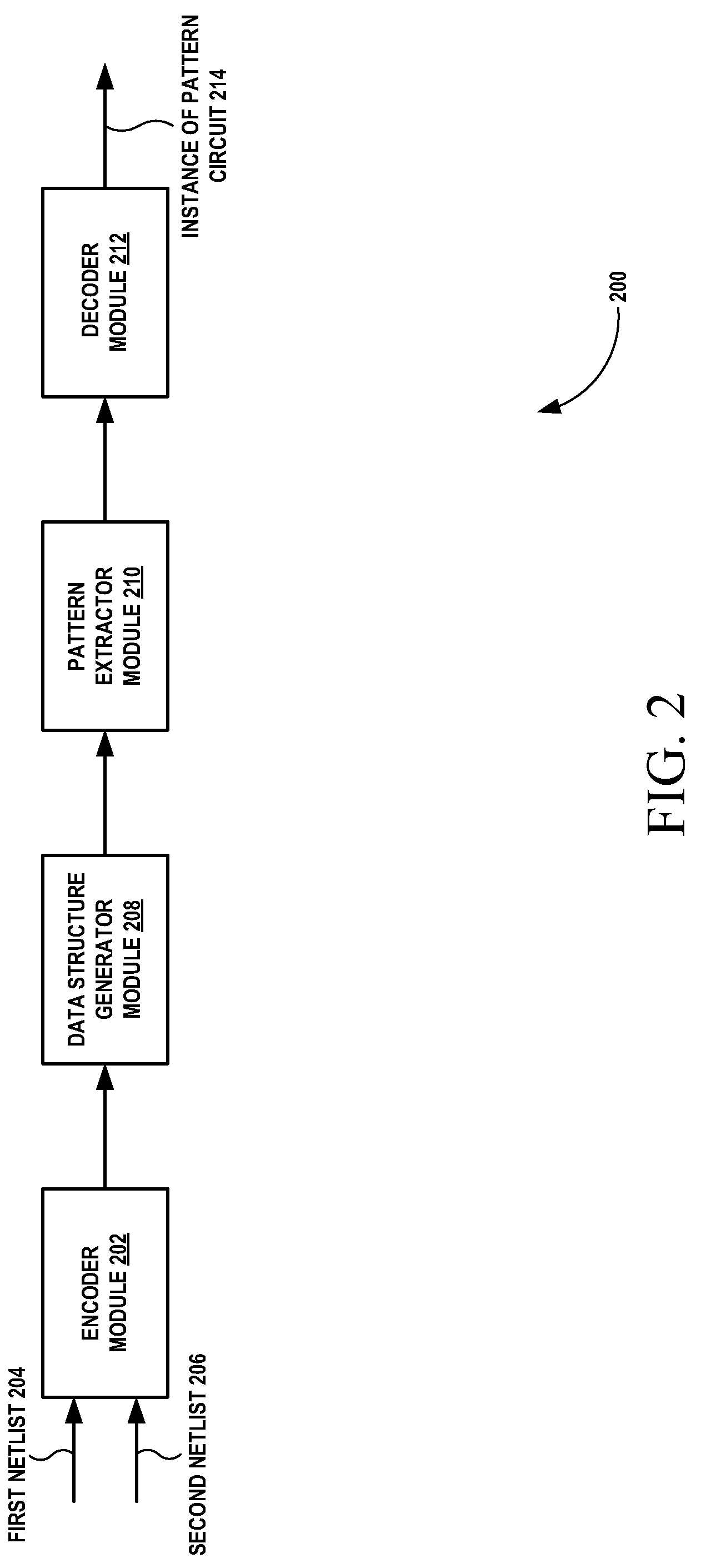
The patent describes a method and system for recognizing a pattern circuit in an integrated circuit design. It involves encoding the pattern circuit and the target circuit, and generating a cross-linked data structure based on attributes and connectivity information of at least two devices and one net from the first netlist. The cross-linked data structure includes a device integer array and a net integer array. The method also involves identifying an instance of the pattern circuit in the target circuit by checking the first target device for pseudo-matching with the first pattern device of the pattern circuit and its neighboring nets. The system can be implemented in any means and can be executed by a machine-readable medium. The technical effect of this patent is to provide a more efficient and accurate way of recognizing pattern circuits in integrated circuit designs.

Problems solved by technology

However, the sub-circuit extraction may not be a straightforward comparison of devices or components present in the pattern circuit to their counterpart devices or components in the large circuit schematic.
Additionally, the computational complexity for the extraction scheme may grow significantly as the size of the pattern circuit or the large circuit schematic increases.

Method used


Image

  • Sub-circuit pattern recognition in integrated circuit design
  • Sub-circuit pattern recognition in integrated circuit design
  • Sub-circuit pattern recognition in integrated circuit design

Examples


Embodiment Construction

[0017]A method and system for sub-circuit pattern recognition in integrated circuit design is disclosed. In the following detailed description of the embodiments of the invention, reference is made to the accompanying drawings that form a part hereof, and in which are shown by way of illustration specific embodiments in which the invention may be practiced. These embodiments are described in sufficient detail to enable those skilled in the art to practice the invention, and it is to be understood that other embodiments may be utilized and that changes may be made without departing from the scope of the present invention. The following detailed description is, therefore, not to be taken in a limiting sense, and the scope of the present invention is defined only by the appended claims.

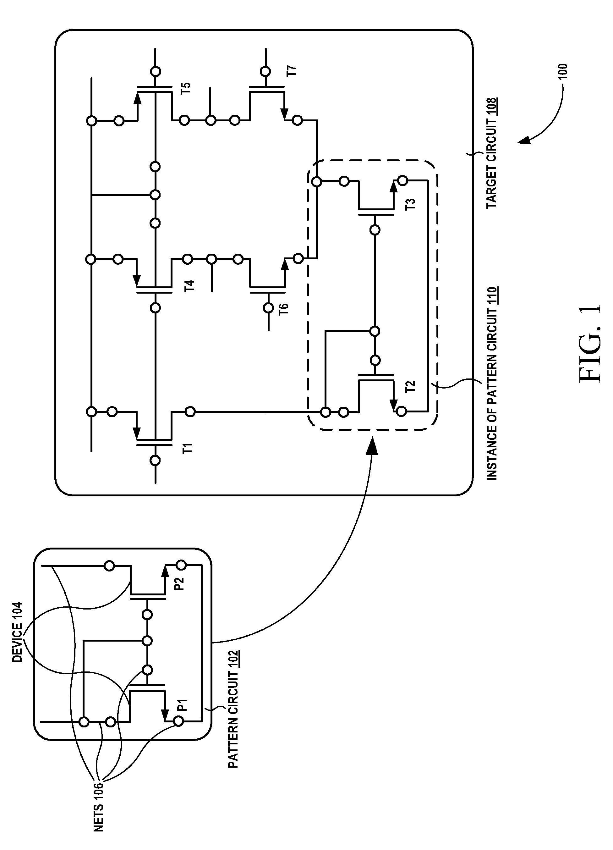
[0018]FIG. 1 is a block diagram 100 of a pattern circuit 102 and a target circuit 108, according to one embodiment. Particularly, FIG. 1 illustrates the pattern circuit 102, the target circuit 108 and an...


PUM


Abstract

A method and system for sub-circuit pattern recognition in integrated circuit design is disclosed. In one embodiment, a method for recognizing a pattern circuit in a target circuit, includes encoding the pattern circuit and the target circuit by processing a first netlist of the pattern circuit and a second netlist of the target circuit, generating a cross-linked data structure based on attributes and connectivity information of at least two devices and at least one net from the first netlist, and identifying an instance of the pattern circuit in the target circuit based on an associative mapping between the pattern circuit and a sub-circuit of the target circuit using a device integer array and a net integer array. Each of the first netlist and the second netlist is based on the at least two devices and the at least one net connecting the at least two devices.

Description

FIELD OF TECHNOLOGY[0001]Embodiments of the present invention relate to the field of electronics. More particularly, embodiments of the present invention relate to a circuit pattern search technique.BACKGROUND[0002]A sub-circuit extraction, which is a special form of the sub-graph isomorphism problem in graph theory, is identification of instances of a pattern circuit in a large circuit schematic. The sub-circuit extraction may be done by checking presence of the pattern circuit in the large circuit schematic. However, the sub-circuit extraction may not be a straightforward comparison of devices or components present in the pattern circuit to their counterpart devices or components in the large circuit schematic. That is, the connectivity between the counterpart devices or components in the large circuit schematic has to topologically match the connectivity of the devices or components in the pattern circuit. Additionally, the computational complexity for the extraction scheme may g...

Claims


Application Information

Patent Timeline
Patent Type & Authority Patents(United States)
IPC IPC(8): G06F9/455G06F17/50
CPCG06F17/5045G06F30/30
Inventor KRISHNAN, SANDEEP SHYLAJA
Owner TEXAS INSTR INC
Learn More