Power generating system with flux regulated generator
a technology of flux regulation and power generation system, applied in the direction of dynamo-electric converter control, magnetic circuit shape/form/construction, magnetic circuit rotating parts, etc., can solve the problems of increasing cost and weigh
- Summary
- Abstract
- Description
- Claims
- Application Information
AI Technical Summary
Benefits of technology
Problems solved by technology
Method used
Image
Examples
first embodiment
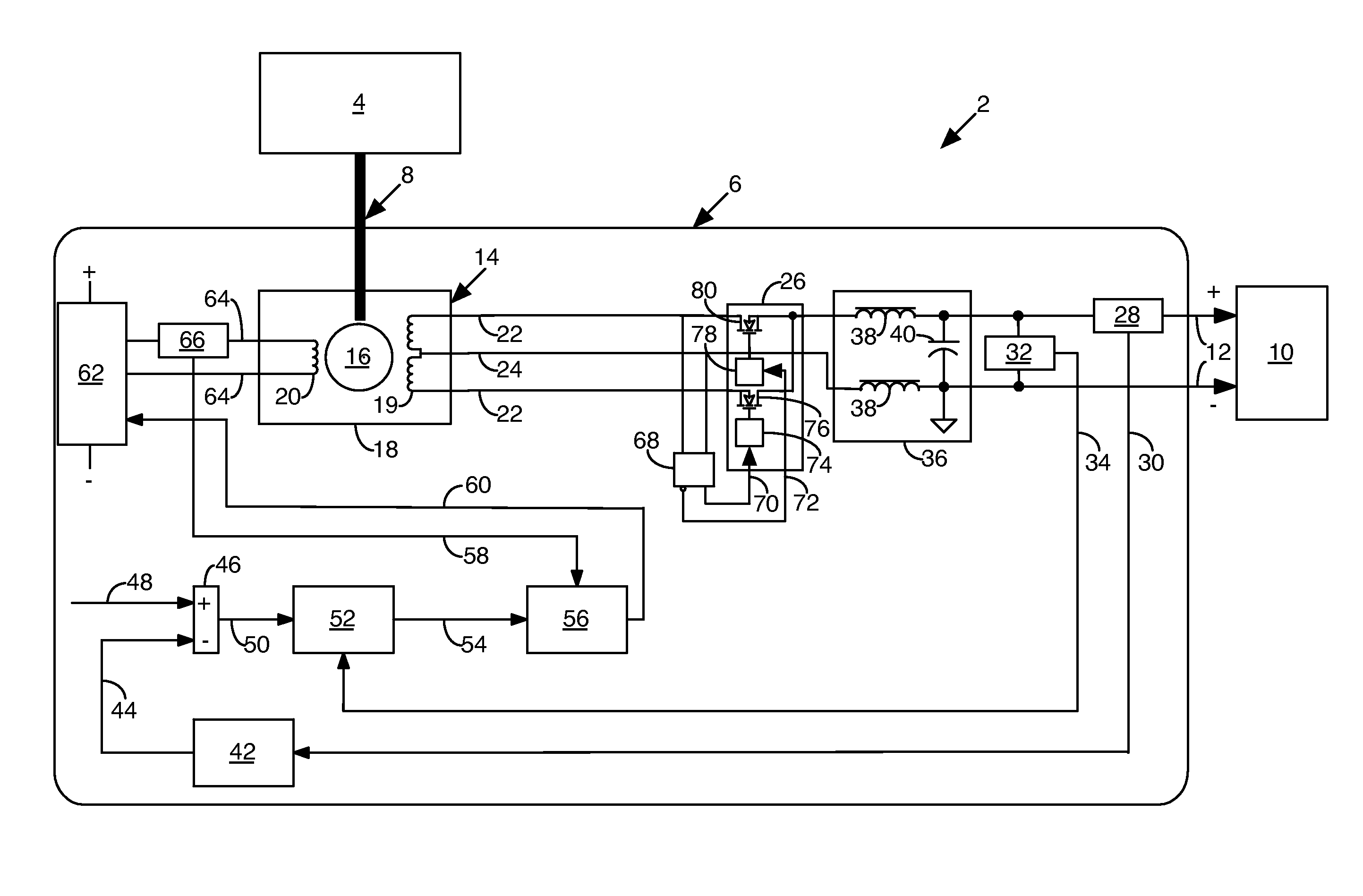
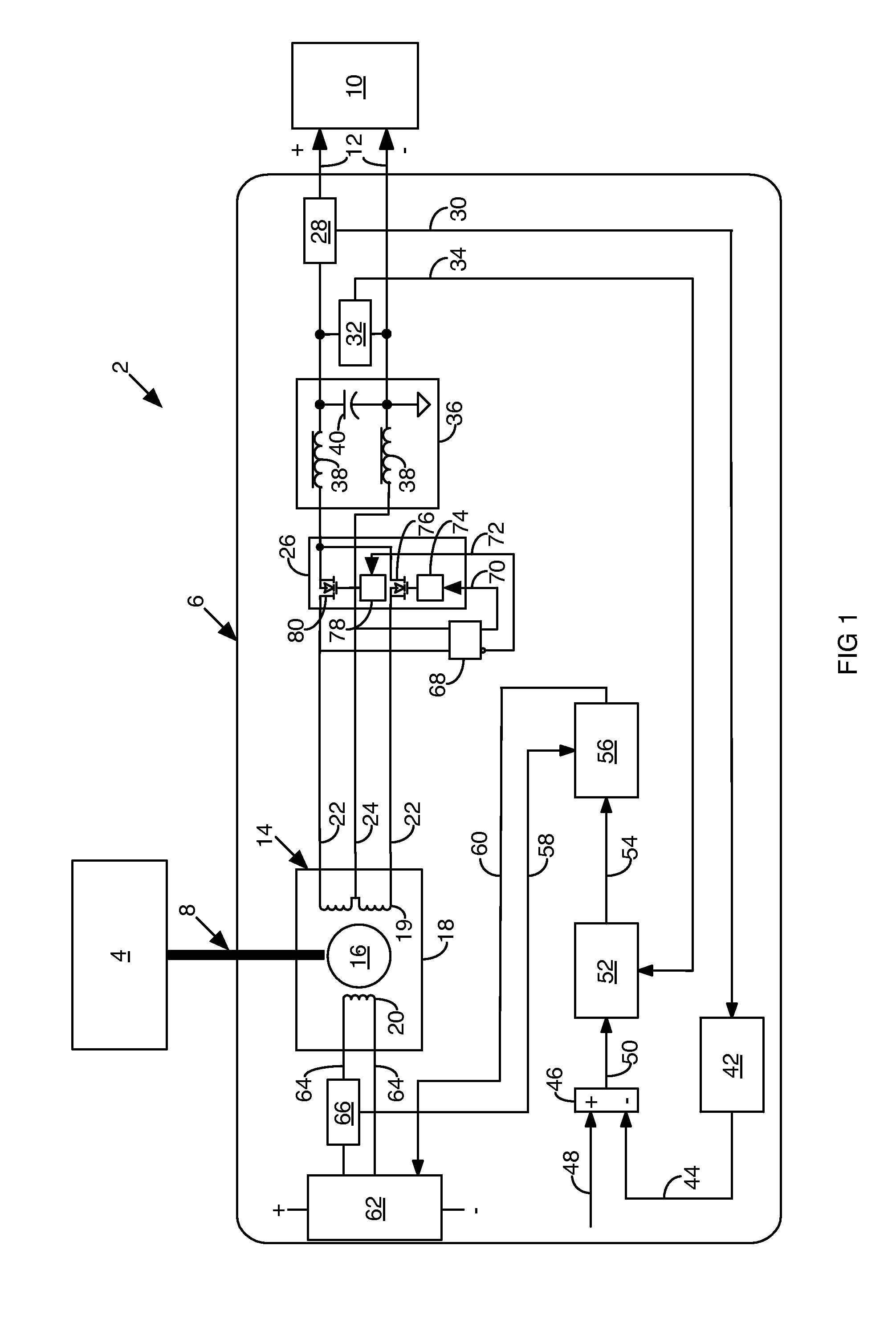
[0009]FIG. 1 is a schematic diagram of a power generation and regulation system 2 according to the invention. The power system 2 comprises a prime mover 4, such as a gas turbine engine, that couples to at least one high frequency alternating current (HFAC) generator module 6 by means of a prime mover drive shaft 8. The HFAC generator module 6 includes a desired direct current (DC) power output that an electrical load 10 receives by way of generator module output lines 12.
[0010]The generator module 6 comprises a single phase controlled permanent magnet machine (PMM) 14 that serves as a HFAC generator, such as of the type described in U.S. Pat. No. 8,085,003to Gieras et al., owned by the assignee of this application and hereby incorporated by reference. Each PMM 14 has a permanent magnet (PM) rotor 16 and a stator 18 with a winding 19 and a magnetic flux diverter circuit 20. The prime mover 4 rotates the PM rotor 16 by way of the prime mover drive shaft 8 at a velocity sufficient to d...
second embodiment
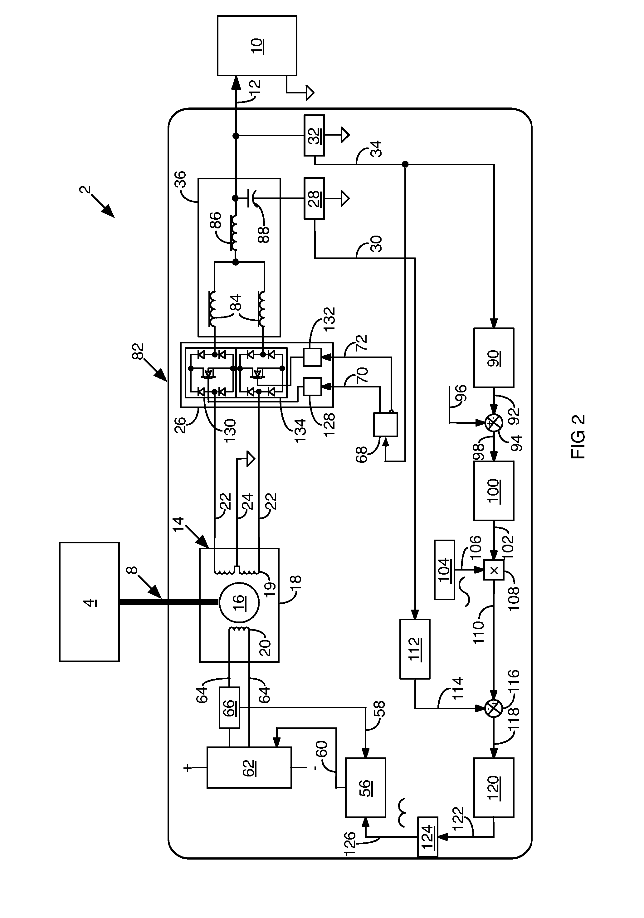
[0033]A single phase sliding mode cycloconverter 144 comprises the power transformation circuit 26, shown as a bi-directional switching circuit in FIG. 4 with the first bi-directional gate drive circuit 128, the first bi-directional switch 130, the second bi-directional gate drive circuit 132 and the second bi-directional switch 134, as described for the invention in connection with FIG. 2. It also comprises an angle generator 146, a sliding mode converter 148 and a signal steering block 150, as described in Nguyen et al. The power transformation circuit 26 receives the HFAC output on the stator output lines 22 and transforms it to a desired low frequency AC power output on a cycloconverter output line 152.
[0034]A low pass filter network 154, similar to the low pass filter network 36 described for the second embodiment of the invention in connection with FIG. 2, comprising the output filter inductor 86, the output filter capacitor 88, the current sensor 28 and the electrical potenti...
PUM
 Abstract
Description
Claims
Application Information
 - R&D
- Intellectual Property
- Life Sciences
- Materials
- Tech Scout
- Unparalleled Data Quality
- Higher Quality Content
- 60% Fewer Hallucinations
Browse by: Latest US Patents, China's latest patents, Technical Efficacy Thesaurus, Application Domain, Technology Topic, Popular Technical Reports.
© 2025 PatSnap. All rights reserved.Legal|Privacy policy|Modern Slavery Act Transparency Statement|Sitemap|About US| Contact US: help@patsnap.com


