
Modular insulated water tank

a water tank and module technology, applied in the field of module insulated water tanks, can solve the problems of difficult installation, bulky insulation, heavy and cumbersome tanks, etc., and achieve the effect of convenient assembly, easy manufacturing, and easy transportation and storag

Inactive Publication Date: 2013-04-30
GOCZE THOMAS
View PDF13 Cites 6 Cited by
  • Summary
  • Abstract
  • Description
  • Claims
  • Application Information

AI Technical Summary

Benefits of technology

The modular design facilitates easy manufacturing, shipping, and installation of large-capacity water tanks that are structurally rigid, efficient in heat retention, and adaptable to various locations, enhancing safety and usability in residential and commercial settings.

Problems solved by technology

The tanks are also often wrapped in bulky insulation.
However, this method of tank construction creates heavy and cumbersome tanks that are difficult to install.
Therefore, traditional water storage tanks were usually limited in size, reducing the amount of heat energy that could be stored and eliminating efficiencies.
In order to use make use of larger quantities of water to store heat energy (say, over 100 gallons), either multiple small tanks were necessary or large tanks were built on site, at substantial cost.
These tanks could store up to 1500 gallons and were relatively easy to install, though time consuming.
However, the water storage tanks of the '594 patent are not structurally rigid, thereby leading to some inherent disadvantages, primarily that they are not designed to bear a load on their covers.
Thus, persons climbing onto or placing objects on top of these tanks could inadvertently cause failure.
Moreover, the substantially circular footprint of these tanks is an inefficient use of floor space.

Method used


Image

  • Modular insulated water tank
  • Modular insulated water tank
  • Modular insulated water tank

Examples


Embodiment Construction

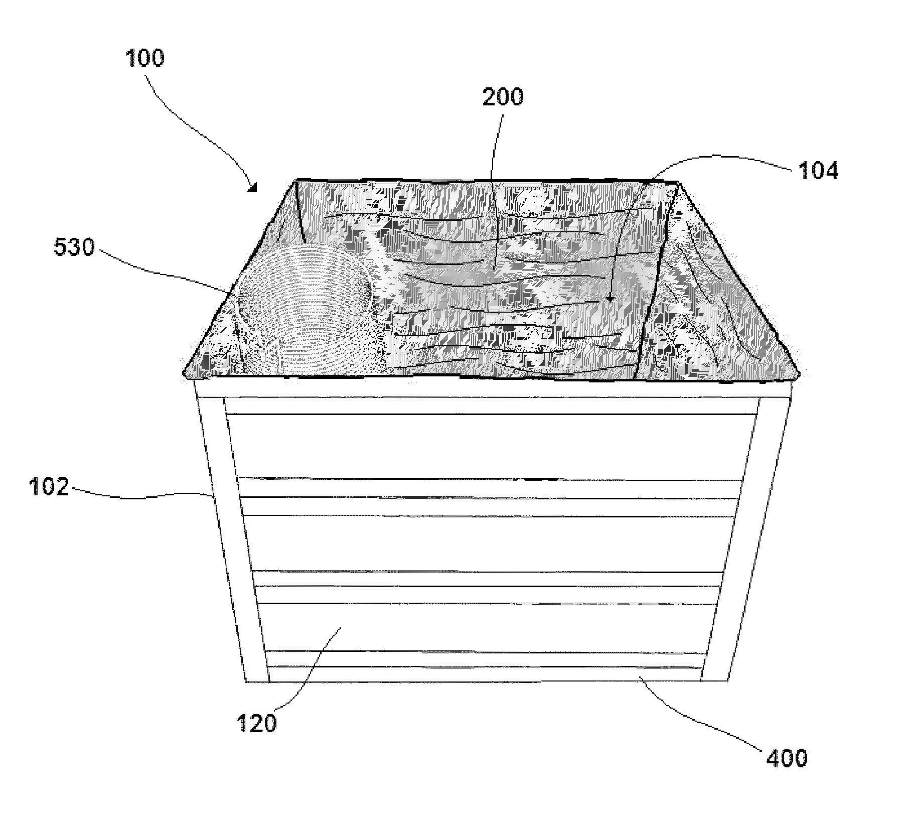
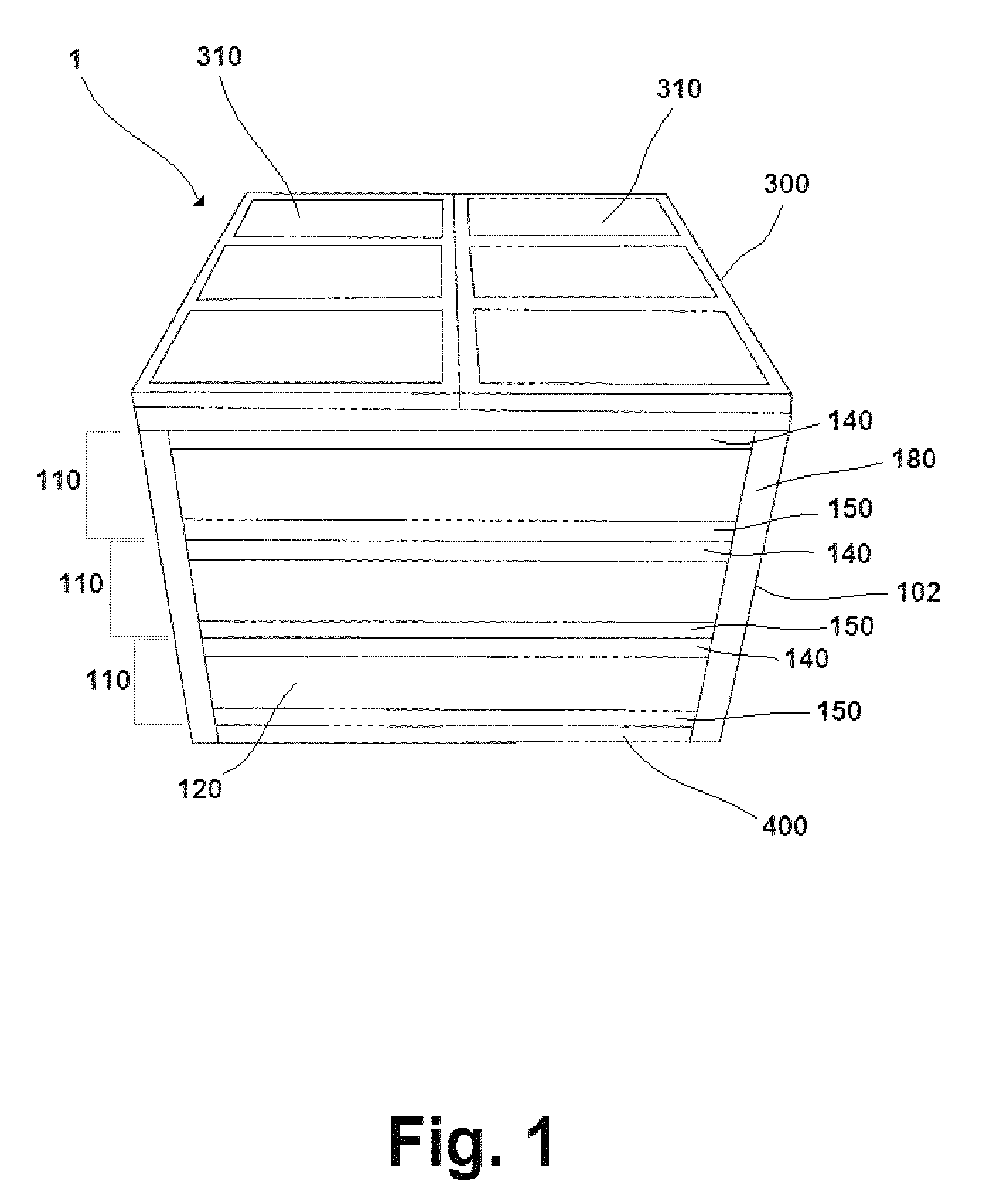
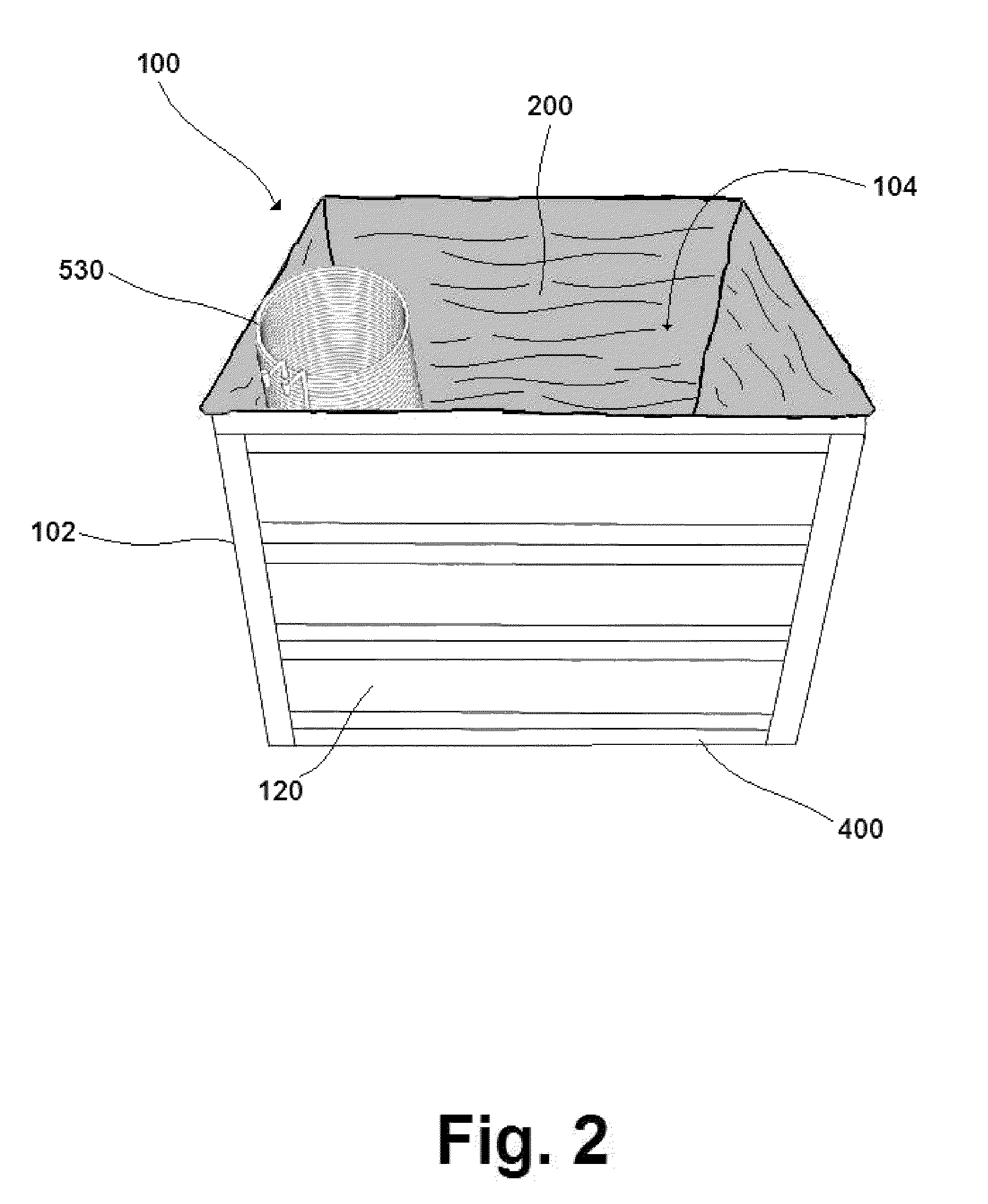
[0027]An aspect of the present invention discloses a modular insulated water tank 1 capable of storing thermally isolated fluid. The water tank 1 comprises a support structure 100, a liner 200, and a cover 300. See FIGS. 1 and 2. The support structure 100 is a substantially hollow enclosure formed of a plurality of substantially rigid sides 102 surrounding an interior 104. It must be capable of containing and supporting the liner 200 within its interior 104 when the liner 200 contains fluid. Moreover, the sides 102 of the support structure 100 must be thermally isolatable, to minimize the loss of heat energy from the fluid contained within the water tank 1. The support structure 100 is further comprised of two or more separable, stackable retention tiers 110. See FIG. 3. Because the retention tiers 110 are separable, the support structure 100 may be broken down for ease of shipment and storage.

[0028]The liner 200 is a flexible container capable of retaining fluids. In the preferred ...


PUM


Abstract

A modular insulated water tank comprising a hollow insulated support structure, a liner, and an insulated cover, with the support structure being comprised of two or more separable, vertically stackable retention tiers, the liner being a flexible container capable of retaining fluids within the interior of the support structure, and the cover being capable of enclosing contents contained within the interior of the water tank. So configured, the modular insulated water tank is capable of retaining a large quantity of fluid, such as water, at an elevated temperature for an extended length of time, for purposes of using the heat energy stored therein for space heating purposes or for domestic hot water use. The modular water tank employs a heating exchange interface comprised of inflow and outflow conduits and a heat exchanger, capable of bringing fluids into and out of the water tank to either release heat energy into the fluid contained in the water tank for heat storage or to absorb heat energy from the fluid contained in the water tank for heat use. The modular design of the water tank allows it to be easily shipped and stored, and assembled in otherwise difficult to access locations. The water tank is intended to be used to store heat energy generated by an external heat source, such as a boiler, solar collectors, or a wood stove.

Description

FIELD OF THE INVENTION[0001]The invention relates generally to environmental climate control devices, namely, heat energy storage devices. Specifically, an aspect of the present invention relates to an improvement on water storage tanks for storing heat energy for residential and commercial use, where the heat energy is produced asynchronously by boilers, solar collectors, wood stoves, and the like. Improvements disclosed in the present invention include a modular configuration of the water tank to allow for easy manufacture, shipping, and storage, as well as easy assembly and disassembly in difficult to access locations.BACKGROUND[0002]Water may be used as a storage medium for heat. In residential and commercial settings, this may be accomplished by use of a water storage tank. The tank is filled with water and then heat energy from an external source, such as solar collectors, geothermal heating, biomass, wood pellets, cogeneration, or even traditional fossil fuels or electrical s...

Claims


Application Information

Patent Timeline
Patent Type & Authority Patents(United States)
IPC IPC(8): F28D20/00
CPCF24H1/182F24H1/183F28D20/0034F28D2001/0273F28D2020/0078Y02E60/142Y02E70/30Y02E60/14Y10T137/6579
Inventor GOCZE, THOMAS
Owner GOCZE THOMAS
Learn More