
Working machine

a technology of working machines and filters, applied in the direction of machines/engines, mechanical equipment, electric control, etc., can solve the problems of needing to work in potentially flammable surroundings, melting damage or thermal damage to filters, etc., and achieve the effect of preventing the accumulation of pm that may damage filters in the working machin

Active Publication Date: 2013-04-30
NIHON KENKI CO LTD
View PDF14 Cites 2 Cited by
  • Summary
  • Abstract
  • Description
  • Claims
  • Application Information

AI Technical Summary

Benefits of technology

The present invention provides a working machine that can prevent damage to its filter by reducing the accumulation of particulate matter (PM) even when the machine needs to be moved to a different location for filter regeneration. This prevents excessive deposition of PM that could damage the filter, ensuring continued proper operation of the machine.

Problems solved by technology

The hydraulic excavators (construction machines) and other working machines driven by a diesel engine may need to work in potentially flammable surroundings.
Combusting PM in excess of the permissible accumulation level is likely to cause melting damage or thermal damage to the filter.

Method used


Image

  • Working machine
  • Working machine
  • Working machine

Examples


Embodiment Construction

[0020]Hereunder, embodiments of the present invention will be described with reference to the accompanying drawings.

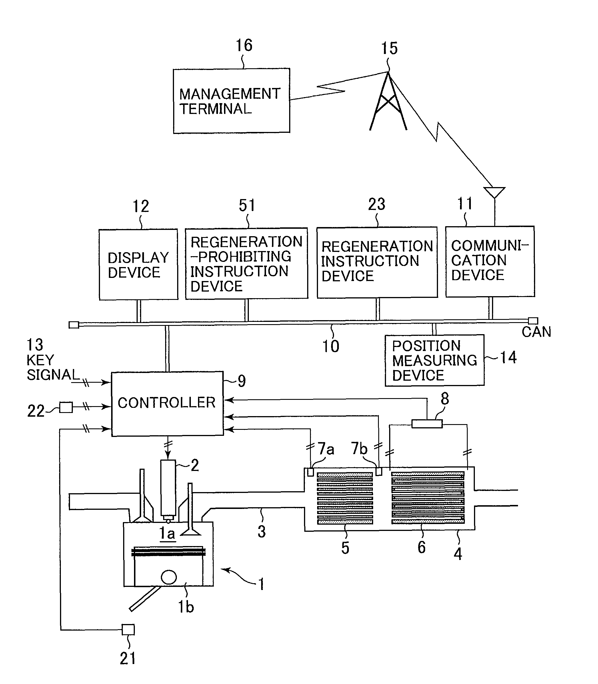
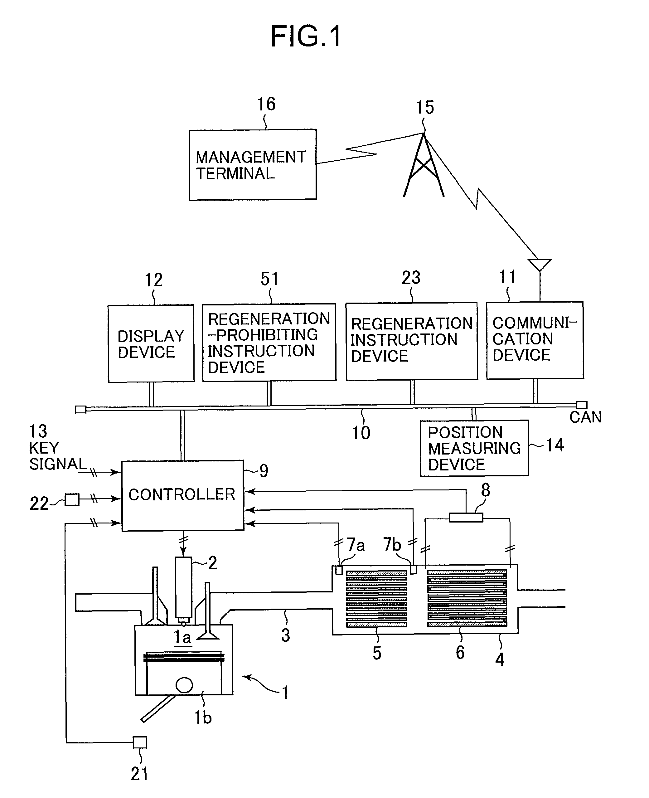
[0021]FIG. 1 is a schematic configuration diagram of a working machine according to a first embodiment of the present invention. The working machine shown in the figure includes a diesel engine 1, an exhaust treatment device 4, a regeneration instruction device 23, a controller (control device) 9, and an alarm device 12.

[0022]The diesel engine (hereinafter referred to simply as the engine) 1 elevates internal air of a combustion chamber (cylinder) 1a to a high temperature by compressing the air with a piston 1b, then causes spontaneous ignition of a fuel supplied to the compressed air via a fuel injector 2, and thus obtains motive power. Exhaust gases from the combustion chamber 1a are introduced into the exhaust treatment device 4 via an exhaust pipe 3 connected to the combustion chamber 1a.

[0023]The exhaust treatment device 4 includes an oxidation catalyst 5 and a c...


PUM


Abstract

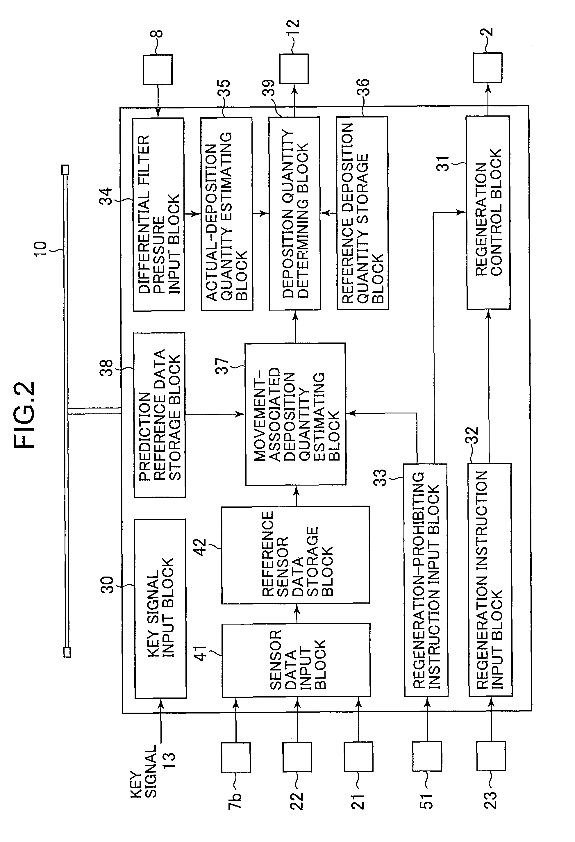
Disclosed is a working machine capable of preventing damage to a filter due to excessive accumulation of particulate matter (PM), even under a situation that requires, prior to compulsory regeneration of the filter, moving the machine to a place in which to perform the regeneration work. The working machine that includes an exhaust treatment device 4 having a filter 6 to trap the PM, a regeneration control section 31 for compulsorily regenerating the filter, and a regeneration instruction device 23 for instructing the regeneration control section 31 to start the compulsory regeneration. Further, when a deposition quantity estimating element determines that an actual PM deposition quantity has reached a deposition alarm level, an alarm device 12 notifies an operator that the time has come to start the movement of the working machine to the place of regeneration.

Description

BACKGROUND OF THE INVENTION[0001]1. Field of the Invention[0002]The present invention relates generally to working machines having a diesel engine. The invention relates more particularly to a working machine used in an environment that requires moving the machine to a place in which to perform regeneration work when an internal filter is subjected to compulsory regeneration.[0003]2. Description of the Related Art[0004]An exhaust treatment device removes particulate matter (hereinafter, referred to as PM) from the exhaust gases of a diesel engine. In some cases, such an exhaust treatment device includes a diesel particulate filter (DPF, which may hereinafter be referred to simply as the filter). In this type of exhaust treatment device, the filter needs to be regenerated by removing accumulated PM timely to avoid an increase in exhaust pressure due to continued PM accumulation.[0005]Methods of filter regeneration includes compulsory regeneration by which the unburnt fuel contained i...

Claims


Application Information

Patent Timeline
Patent Type & Authority Patents(United States)
IPC IPC(8): F01N3/00F01N3/02
CPCF01N3/023F01N3/0232F01N9/002F02D41/029F01N2900/1606Y02T10/47F02D2041/228F02D2200/0812F02D2200/701F02D2200/702Y02T10/40
Inventor SHIBAMORI, KAZUHIRONAKAMURA, KAZUNORIISHIKAWA, KOUJIKOWATARI, YOICHITSUKADA, HIDENOBUKAMIYA, SHOHEIEZAWA, MASANORI
Owner NIHON KENKI CO LTD
Learn More