
Target detecting and determining method for detecting and determining target based on height information and storage medium for storing program executing target detecting and determining method

a technology of height information and target detection, applied in the direction of optical radiation measurement, instruments for comonautical navigation, etc., can solve the problems of lowering the reliability of burglarproof systems, difficult to avoid the occurrence of a plurality of undetectable areas in the guarding area, etc., to reduce misdetection and widen the detection range

Active Publication Date: 2013-04-16
OPTEX CO LTD
View PDF14 Cites 1 Cited by
  • Summary
  • Abstract
  • Description
  • Claims
  • Application Information

AI Technical Summary

Benefits of technology

The present invention is a device, method, and program for target detection using a laser sensor. The device emits a laser beam diagonally downward from an installing position, and obtains distance information to an object being detected. When the object reaches the emitting position, the device decides whether it is a target or a non-target based on the distance information. The method and program can reduce misdetection while maintaining a wide detecting range. The device / method / program can be used in various applications, such as security or autonomous vehicles.

Problems solved by technology

The detecting device often detects the small animal as the human to output a human body detecting signal, resulting in lowering of the reliability of the burglarproof system.
When the laser sensor is installed horizontally in a low position and an obstruction of about the height of the human exists between the laser sensor and the guarding area, it is difficult to avoid occurrence of a plurality of undetectable areas in the guarding area.

Method used


Image

  • Target detecting and determining method for detecting and determining target based on height information and storage medium for storing program executing target detecting and determining method
  • Target detecting and determining method for detecting and determining target based on height information and storage medium for storing program executing target detecting and determining method
  • Target detecting and determining method for detecting and determining target based on height information and storage medium for storing program executing target detecting and determining method

Examples


first embodiment

1. First Embodiment

(1) Configuration of a Laser Sensor Device

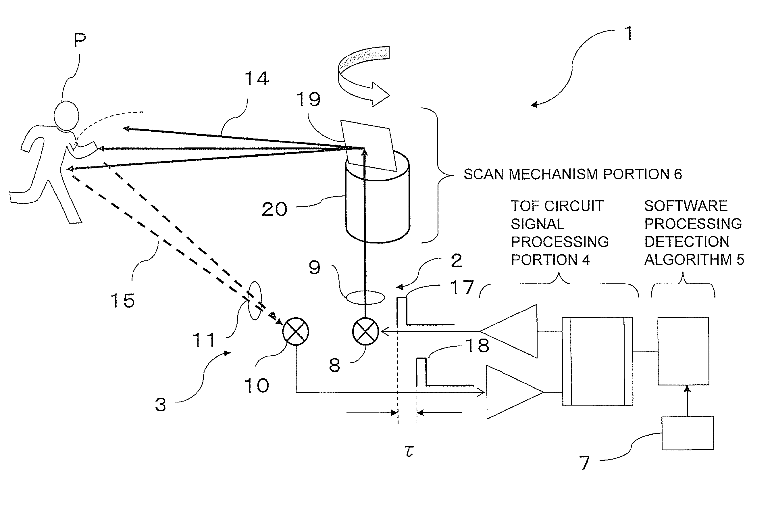
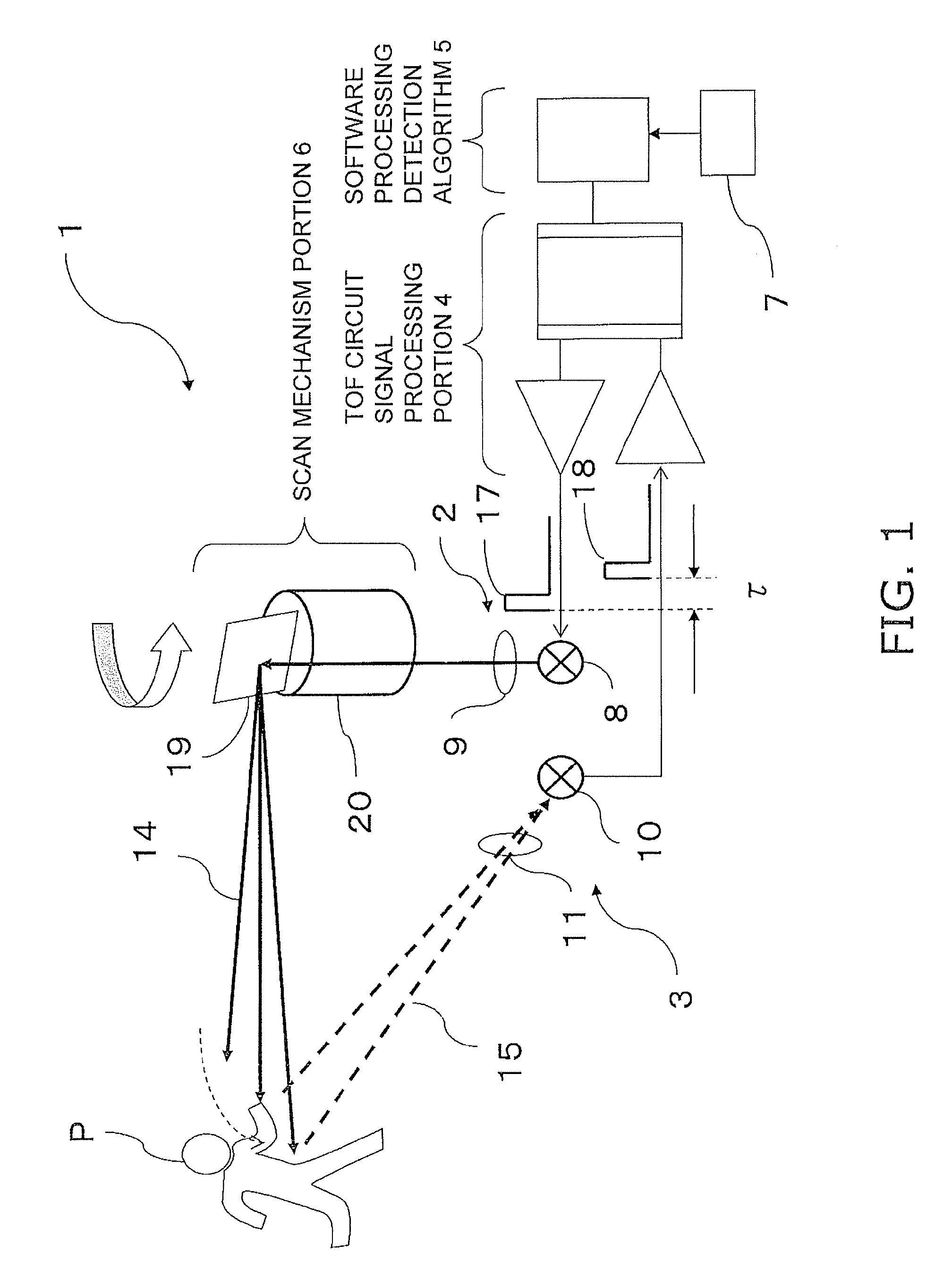
[0037]FIG. 1 is a block diagram illustrating a schematic configuration of a laser sensor device 1 according to an embodiment of the present invention. The laser sensor device 1 is a device which emits a laser beam and then receives reflection light from a target to detect the target. The laser sensor device 1 is mainly used for burglar prevention in an area or a space having a predetermined range, such as a periphery of an entrance of a building, an open space, and an outside of a fence. Specifically, the laser sensor device 1 is used for detecting an existence of an intruder in the guarding area.

[0038]The laser sensor device 1 is combined with an alarm device and an image displaying device to configure a burglarproof system. The alarm device permits lighting or flashing of an illuminating lamp and sounding of an alarm buzzer or a siren. In some cases, the alarm device transmits an alarm signal to a facility to be guarded ...


PUM


Abstract

In a target detecting technique using a laser sensor, misdetection can be reduced while maintaining a wide detecting range. A target detecting method for detecting a target by emitting a laser beam diagonally downward from an installing position of a laser emitting and receiving portion. The method includes the steps of: obtaining distance information from the laser emitting and receiving portion to an object to be detected; determining, when the object to be detected approaches the laser emitting and receiving portion, whether the tracking of the object to be detected is stopped or not; and determining, when the tracking of the object to be detected is stopped, whether the object to be detected is the target or a non-target based on distance information immediately before the tracking of the object to be detected is stopped.

Description

CROSS-REFERENCE TO RELATED APPLICATIONS[0001]This application claims priority under 35 U.S.C. §119 to Japanese Patent Application No. 2007-279651 filed on Oct. 26, 2007. The entire disclosure of Japanese Patent Application No. 2007-279651 is hereby incorporated herein by reference.BACKGROUND OF THE INVENTION[0002]1. Field of the Invention[0003]The present invention relates to a target detecting device, a target detecting method, and a target detecting program, which detect a target. More specifically, the present invention relates to a target detecting device, a target detecting method, and a target detecting program, which detect a target by emitting and receiving a laser beam.[0004]2. Background Information[0005]A burglarproof system typically has a detecting device which detects a human who intrudes into a predetermined guarding area (hereinafter, referred to as an “intruder”), and an alarm generating device which generates an alarm based on a detected result. The detecting devic...

Claims


Application Information

Patent Timeline
Patent Type & Authority Patents(United States)
IPC IPC(8): G06M7/00G01J1/20G01S17/04
CPCG01S7/4802G01S17/026G01S17/66G08B13/184G01S17/04
Inventor IWASAWA, MASASHI
Owner OPTEX CO LTD
Learn More