
Devices and methods for directing migration of non-aqueous phase liquids from sediment

Active Publication Date: 2013-04-16
TRC ENVIRONMENTAL CORP
View PDF6 Cites 5 Cited by
  • Summary
  • Abstract
  • Description
  • Claims
  • Application Information

AI Technical Summary

Benefits of technology

The patent describes a method for directing a chemical called NAPL (or other contaminants) from sediment beneath a body of water towards a specific area. This is done by using a device that allows gas and the contaminants to pass through while blocking the rest of the sediment. The device has a layer that prevents the contaminants from percolating through it. The accumulation zone where the contaminants are directed can contain a layer that allows the gas to be released while leaving the contaminants behind. Various techniques can be used to treat the accumulated contaminants. The device used for directing the contaminant migration can be constructed in more detail based on the mode of contaminant migration (e.g. control layer, grading layer, armoring layer, or transmission layer). Overall, this method helps to contain and remedy contaminant migration, reducing the risk of environmental contamination.

Problems solved by technology

Consequently, they are not water-soluble and form a separate phase when mixed with water.
The sheen and NAPL droplets then are able to migrate along the water surface, creating a potential human health hazard and environmental hazard (e.g., coal tar is a known human carcinogen).
Occasionally, NAPL droplets lose their buoyancy when the gas is lost or when the surface tension of the water is broken.

Method used


Image

  • Devices and methods for directing migration of non-aqueous phase liquids from sediment
  • Devices and methods for directing migration of non-aqueous phase liquids from sediment
  • Devices and methods for directing migration of non-aqueous phase liquids from sediment

Examples


example 1

Utility of a Sand Layer for Directing NAPL Migration from NAPL-Contaminated Sediment During Ebullition

[0035]NAPL migration from sediments to the surface of water bodies has been reported frequently at sites with NAPL-contaminated sediments, such as sediments contaminated with coal tar and creosote. Transport of NAPLs from NAPL-contaminated sediment is facilitated by gas ebullition caused by anaerobic biodegradation of organic matter in the sediment. A remedy often specified for these sites is a sand cap or a sand cap amended with sorbent materials (e.g., coke breeze or organoclays), or a reactive core mat (RCM) consisting of a geomembrane sandwiched around a reactive layer containing sorbent material such as organoclay. However, through testing, I recognized that such an art-recognized sand cap or RCM for controlling NAPL migration was not effective.

[0036]I used a laboratory study to assess the effectiveness of a sand layer for directing NAPL migration from a NAPL-contaminated sedim...

example 2

(Prophetic): Utility of a Sloped Layer for Directing NAPL Migration from NAPL-Contaminated Sediment During Ebulliton

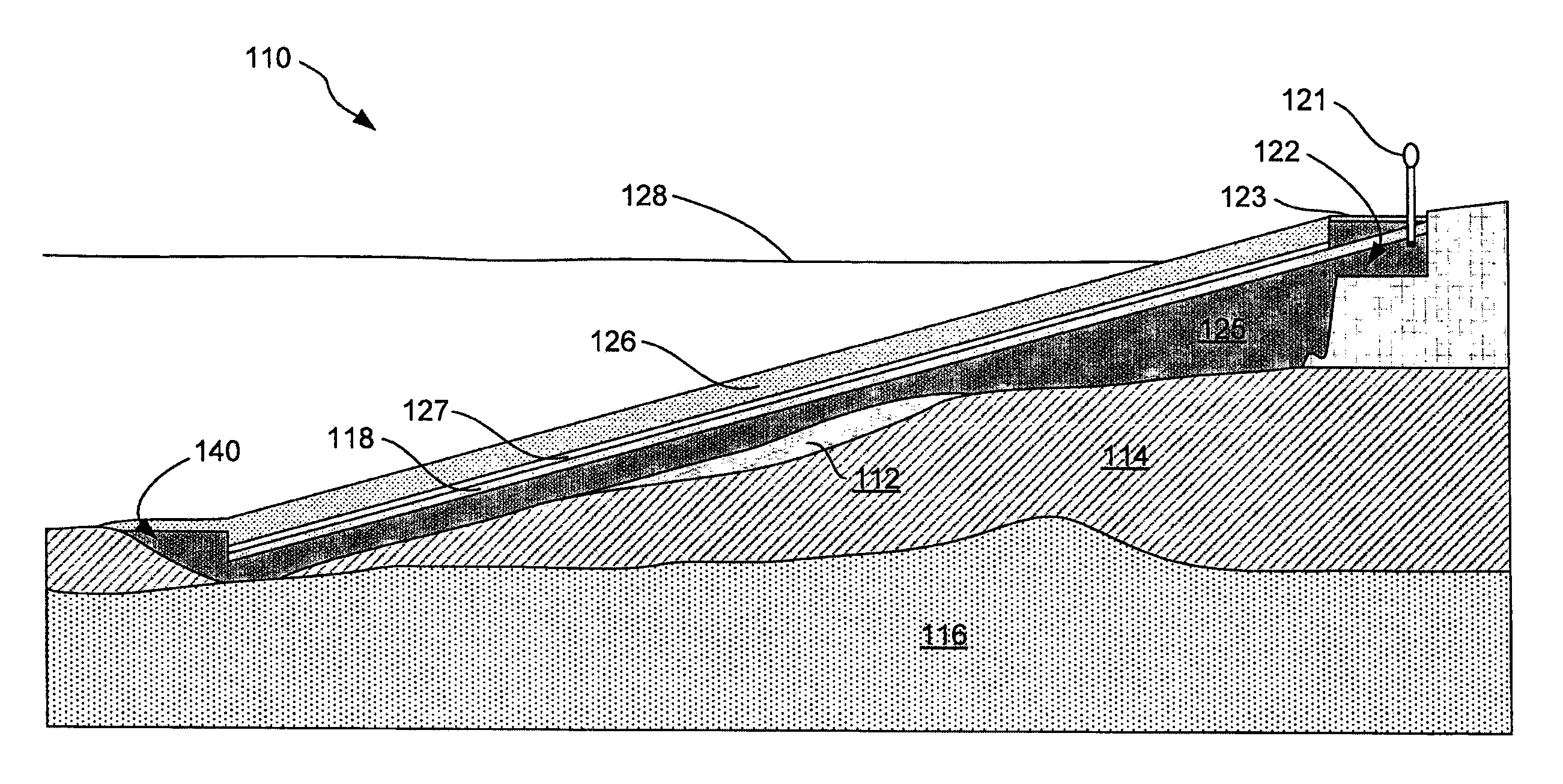
[0038]This example describes the utility of a sloped layer in treatment of a sediment having a tar deposit. By way of example, the inventor determined dimensions of a tar deposit based on results of a field sampling program at a large river having a daily average flow of 400 m3 / s, and a peak flow in excess of 4,000 m3 / s. The estimated velocity at the riverbed varied between 0 m / s at slack tide to nearly 3 m / s during extremely high flow. A bulkhead at the upstream edge of the cove created a large eddy where the river velocity was much less than in the main channel of the river. The sediment textures in the riverbed were characteristic of a high-energy environment—well- to poorly graded gravel with cobbles in the main channel of the river, and silty sand to well-graded gravel in the lee of the bulkhead.

[0039]Organic material in sediment in the lee of the bulkhead include...


PUM


Abstract

Devices and methods for directing a non-aqueous phase liquid (NAPL) that migrate entrained in a fluid (e.g., a gas) from sediments in bodies of water by using trapping caps having an upwardly sloped surface toward an accumulation zone that contains a water table, in which migration of the gas carries the NAPL toward the accumulation zone.

Description

CROSS-REFERENCE TO RELATED APPLICATIONS[0001]This application is a continuation-in-part of U.S. patent application Ser. No. 12 / 259,017, filed Oct. 27, 2008 now abandoned, and entitled “DEVICES AND METHODS FOR DIRECTING MIGRATION OF NON-AQUEOUS PHASE LIQUIDS FROM SEDIMENT,” which claims the benefit of U.S. Provisional Patent Application No. 60 / 982,626 filed Oct. 25, 2007, the disclosure of which is hereby incorporated by reference.STATEMENT REGARDING FEDERALLY SPONSORED RESEARCH OR DEVELOPMENT[0002]Not applicable.BACKGROUND[0003]The invention relates generally to methods for directing migration of non-aqueous phase liquids (NAPLs) from NAPL-contaminated sediment, and relates more particularly to methods of directing NAPL migration from such sediment to the surface of a body of water using devices through which NAPLs and other contaminants cannot percolate. The invention also contemplates directing migration of other granular materials that may contain contaminants, such as sand and s...

Claims


Application Information

Patent Timeline
IPC IPC(8): B09C1/00
CPCB09B3/0025B09B3/0033B09B3/0041B09C1/005B09C1/08B09B3/21B09B3/25B09B3/20
Inventor MCLINN, EUGENE L.RICE, JOHN
Owner TRC ENVIRONMENTAL CORP
Learn More