Combination castor brake system whose castor assemblies are braked and positioned simultaneously

a brake system and castor technology, applied in the field of wheeled vehicles, can solve the problems of inconvenient locking and unlocking of the castors for the user, and achieve the effect of controlling the castor assemblies easily and quickly

Inactive Publication Date: 2013-04-16
SUNNY CASTORS
View PDF65 Cites 16 Cited by
  • Summary
  • Abstract
  • Description
  • Claims
  • Application Information

AI Technical Summary

Benefits of technology

[0007]According to the primary advantage of the present invention, the linking device can drive and operate the castor assemblies so as to brake and position the castor assemblies simultaneously, thereby facilitating a user operating the castor assemblies.
[0008]According to another advantage of the present invention, the user only needs to drive the linking device so as to operate the castor assemblies simultaneously so that the user can control the castor assemblies easily and quickly.
[0009]Further benefits and advantages of the present invention will become apparent after a careful reading of the detailed description with appropriate reference to the accompanying drawings.
[0010]FIG. 1 is a partially perspective view of a combination castor brake system in accordance with the preferred embodiment of the present invention.
[0011]FIG. 2 is an exploded perspective view of the combination castor brake system as shown in FIG. 1.
[0012]FIG. 3 is a perspective view of a braking member of the combination castor brake system as shown in FIG. 1.

Problems solved by technology

However, the castors are controlled by the braking devices respectively so that a user has to lock each of the braking devices respectively so as to brake and position each of the castors and has to unlock each of the braking devices respectively so as to release each of the castors, thereby greatly causing inconvenience to the user when locking and unlocking the castors.

Method used


Image

  • Combination castor brake system whose castor assemblies are braked and positioned simultaneously
  • Combination castor brake system whose castor assemblies are braked and positioned simultaneously
  • Combination castor brake system whose castor assemblies are braked and positioned simultaneously

Examples


Embodiment Construction

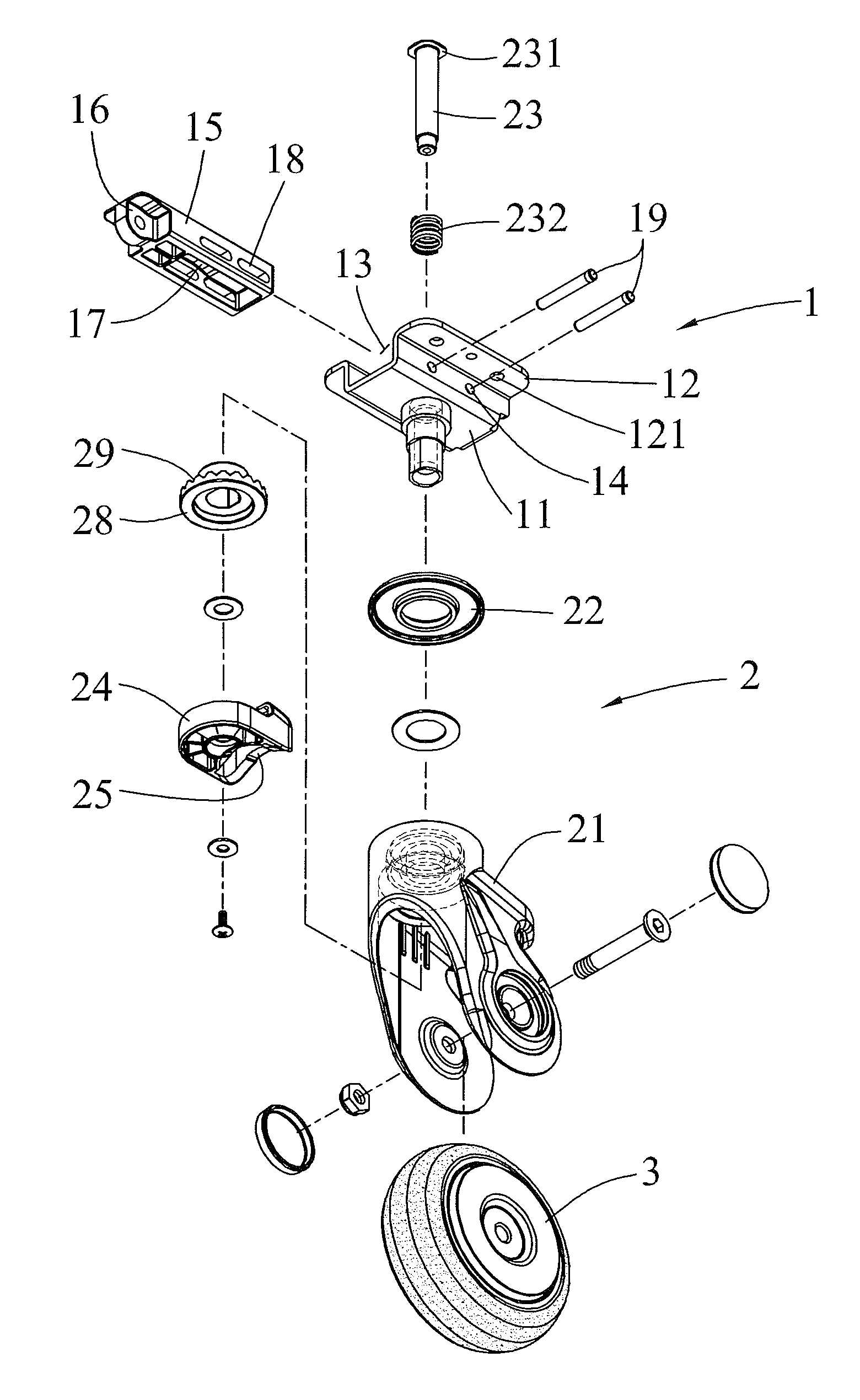
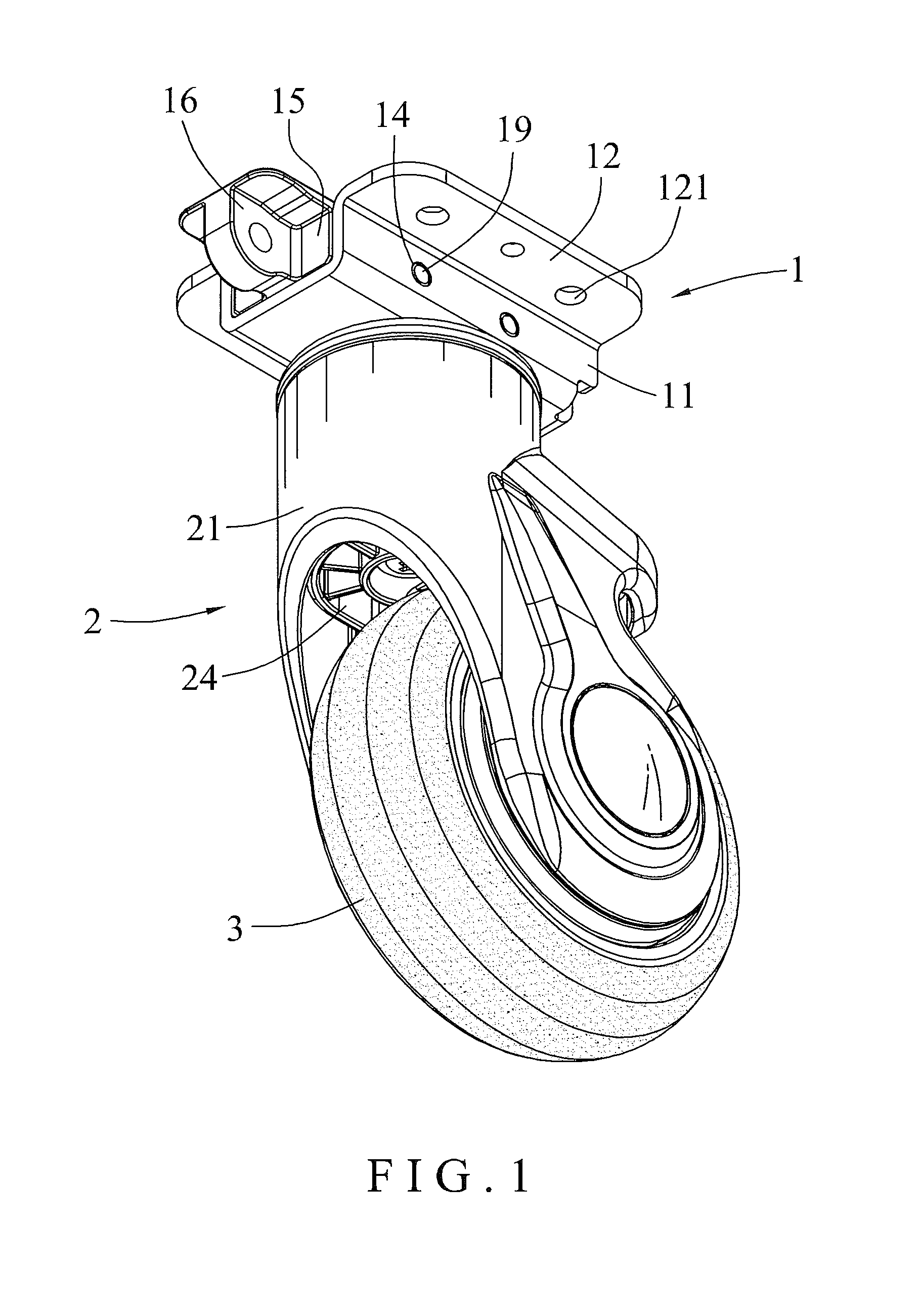
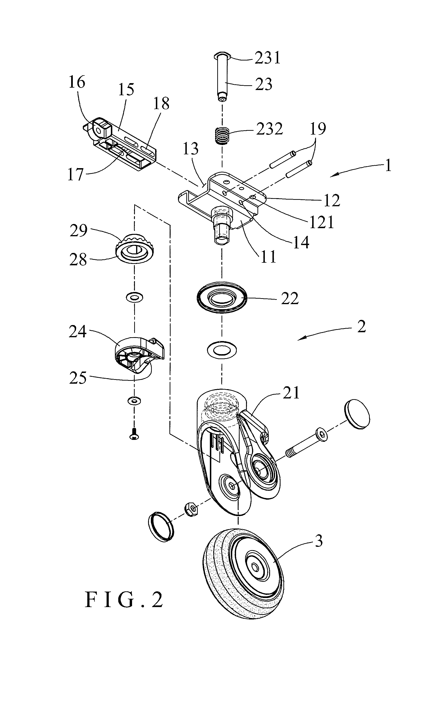
[0019]Referring to the drawings and initially to FIGS. 1-5, a combination castor brake system in accordance with the preferred embodiment of the present invention comprises a linking device 4, and a plurality of castor assemblies connected with the linking device 4.

[0020]Each of the castor brake system assemblies comprises an operation unit 1, a braking unit 2 connected with the operation unit 1, and at least one roller 3 connected with the braking unit 2.

[0021]The operation unit 1 of each of the castor assemblies includes a mounting seat 11 having an interior provided with a slideway 13, a slide 15 slidably mounted in the slideway 13 of the mounting seat 11 and having a first end provided with a connecting portion 16 pivotally connected with the linking device 4 and a second end provided with a pressing ramp 17, and at least two limit rods 19 each extended through the mounting seat 11 and the slide 15.

[0022]The mounting seat 11 of the operation unit 1 is attached to the bottom of a...


PUM


Abstract

A combination castor brake system includes a linking device, and a plurality of castor assemblies connected with the linking device. Each of the castor assemblies includes an operation unit, a braking unit connected with the operation unit, and at least one roller connected with the braking unit. The operation unit of each of the castor assemblies includes a mounting seat, a slide, and at least two limit rods. The braking unit of each of the castor assemblies includes a housing, a top cap, a control shaft, an elastic member, and a braking member. The roller of each of the castor assemblies is rotatably mounted on the housing of the braking unit. Thus, the linking device can drive and operate the castor assemblies to brake and position the castor assemblies simultaneously.

Description

BACKGROUND OF THE INVENTION[0001]1. Field of the Invention[0002]The present invention relates to a wheeled vehicle and, more particularly, to a combination castor brake system for a cart, stroller, chair, wheelchair, patient bed, shelf, cabinet and the like.[0003]2. Description of the Related Art[0004]A conventional wheeled vehicle, such as a cart, stroller, chair and the like, comprises a main frame, a plurality of castors mounted on the bottom of the main frame, and a plurality of braking devices mounted on a respective one of the castors to brake and position each of the castors. However, the castors are controlled by the braking devices respectively so that a user has to lock each of the braking devices respectively so as to brake and position each of the castors and has to unlock each of the braking devices respectively so as to release each of the castors, thereby greatly causing inconvenience to the user when locking and unlocking the castors.BRIEF SUMMARY OF THE INVENTION[00...

Claims


Application Information

Patent Timeline
Patent Type & Authority Patents(United States)
IPC IPC(8): B60B33/00
CPCB60B33/0084B60B33/0092B60B2200/43Y10T16/195B60B2900/531Y10T16/196B60B2900/3312
Inventor LIN, MING-HSIENYANG, FENG-HSI
Owner SUNNY CASTORS
Why Eureka
Try Eureka