Sensor assembly validation

a sensor and assembly technology, applied in the field of meters, can solve the problems of vibrating meter not meeting the micro motion standards, customers may be confused, and manufacturers still face competition by “knock-off” sensor assemblies

Active Publication Date: 2020-03-24
MICRO MOTION INC
View PDF24 Cites 0 Cited by
  • Summary
  • Abstract
  • Description
  • Claims
  • Application Information

AI Technical Summary

Benefits of technology

[0018]Preferably, the method further comprises a step of preventing a meter electronics of the meter in communication with the sensor assembly from operating with the sensor assembly if the sensor assembly is invalid.

Problems solved by technology

One problem faced by users of meters is the ability to correctly identify the particular sensor component being used with the meter electronics.
However, while these prior art approaches can identify various types of sensors, manufacturers still face competition by “knock-off” sensor assemblies, i.e., unauthorized copies of sensor assemblies, that are used with the manufacturer's meter electronics.
Customers may be confused and believe they are using a particular manufacturer's meter, when in fact, they are using only a portion of the manufacturer's meter.
As a result, the vibrating meter will not perform according to Micro Motion's standards.
This not only reduces the sales by the manufacturer, but can also weaken the manufacturer's brand name recognition if the knock-off sensor does not meet the manufacturer's quality and accuracy standards.
The problem with this approach is that the sensor type is simply selected by the calibration values that most closely match the stored values.
Therefore, even if the calibration values received by the meter electronics do not match a stored value corresponding to a particular sensor type, the system simply assumes that the sensor comprises the sensor type with the closest calibration values and that the error is due to some anomaly in the manufacturing process or calibration process.

Method used


Image

  • Sensor assembly validation
  • Sensor assembly validation
  • Sensor assembly validation

Examples


Embodiment Construction

[0039]FIGS. 1-4 and the following description depict specific examples to teach those skilled in the art how to make and use the best mode of the invention. For the purpose of teaching inventive principles, some conventional aspects have been simplified or omitted. Those skilled in the art will appreciate variations from these examples that fall within the scope of the invention. Those skilled in the art will appreciate that the features described below can be combined in various ways to form multiple variations of the invention. As a result, the invention is not limited to the specific examples described below, but only by the claims and their equivalents.

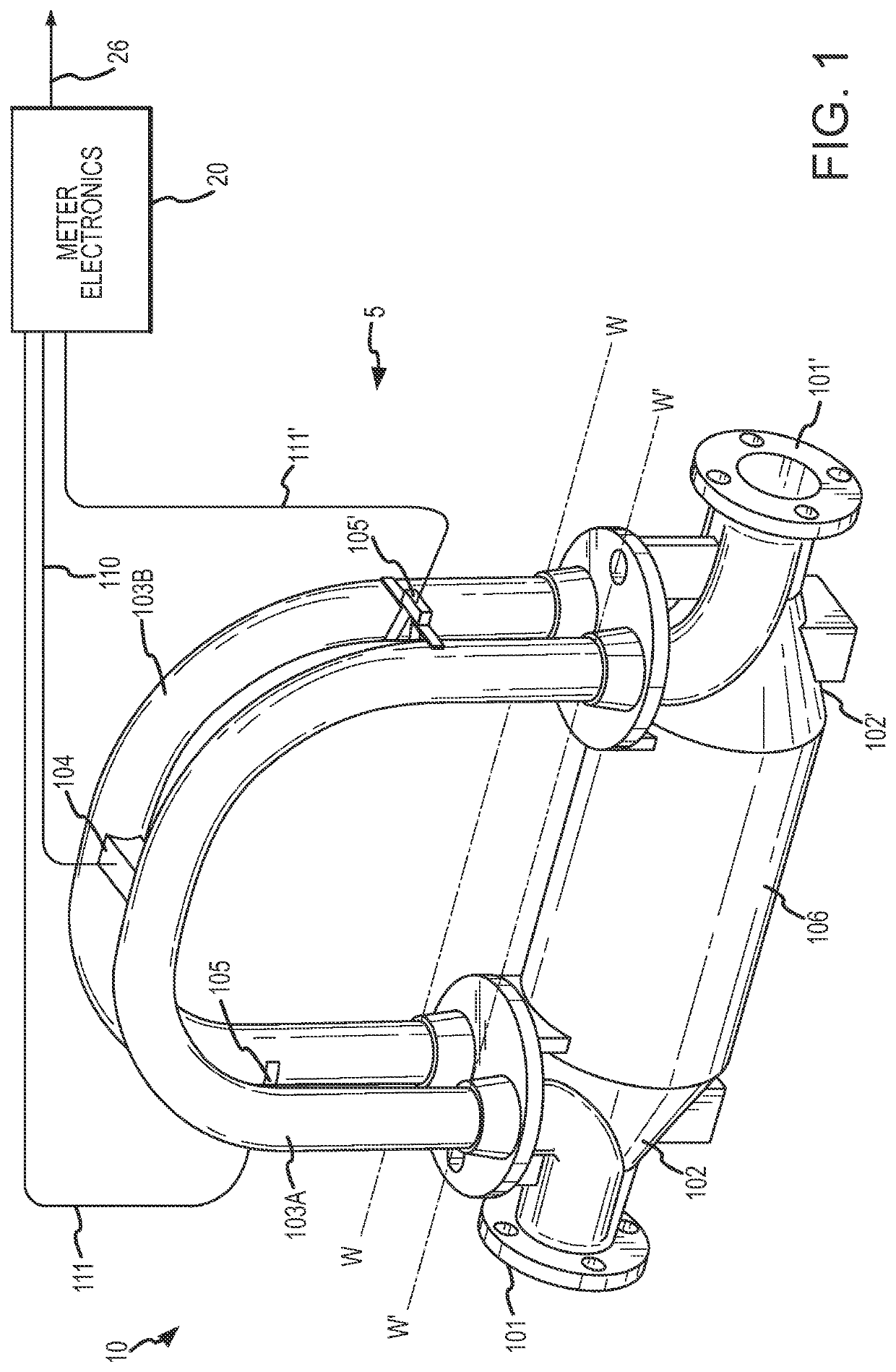
[0040]FIG. 1 shows a vibrating meter 5 in the form of a Coriolis flow meter comprising a sensor assembly 10 and a meter electronics 20 according to an embodiment of the invention. The sensor assembly 10 receives a flowing fluid in the embodiment shown; however, sensor assemblies of meters are not necessarily limited to a structure...


PUM


Abstract

A method for validating a sensor assembly of a meter is provided. The method comprises a step of receiving one or more sensor calibration values. The method further comprises a step of comparing the received sensor calibration values to one or more known sensor calibration values. The method can then validate the sensor assembly if the one or more received sensor calibration values are within a predetermined tolerance of the one or more known sensor calibration values.

Description

TECHNICAL FIELD[0001]The present invention relates to, meters, and more particularly, to a method and apparatus for validating a sensor assembly of a meter.BACKGROUND OF THE INVENTION[0002]Vibrating meters, such as for example, vibrating densitometers and Coriolis flow meters are generally known and are used to measure mass flow and other information for materials within a conduit. The meter comprises a sensor assembly and an electronics portion. The material within the sensor assembly may be flowing or stationary. Each type of sensor may have unique characteristics, which a meter must account for in order to achieve optimum performance. For example, some sensors may require a flow tube apparatus to vibrate at particular displacement levels. Other sensor assembly types may require special compensation algorithms.[0003]The meter electronics typically include stored sensor calibration values for the particular sensor being used. The meter electronics uses these sensor calibration valu...

Claims


Application Information

Patent Timeline
Patent Type & Authority Patents(United States)
IPC IPC(8): G01D18/00G01F1/84G01F25/00
CPCG01D18/00G01F1/8477G01F25/0007G01F25/10G01F25/00G01F1/84
Inventor HAYS, PAUL JMCANALLY, CRAIG B
Owner MICRO MOTION INC
Why Eureka
Try Eureka