Door mirror and assembly method therefor

a door mirror and assembly method technology, applied in the field of vehicle door mirrors and assembly methods therefor, can solve the problems of complicated assembly operations and difficult automation, and achieve the effects of easy assembly, easy automation of assembly operations, and convenient assembly

Active Publication Date: 2014-04-29
MURAKAMI CORP
View PDF13 Cites 6 Cited by
  • Summary
  • Abstract
  • Description
  • Claims
  • Application Information

AI Technical Summary

Benefits of technology

[0007]The present invention has been made in view of the above points and has an object to provide a vehicle door mirror and assembly method therefor with improved assembly performance.
[0008]The present invention provides a manually retractable door mirror comprising: a housing support member provided with a shaft formed protruding downward and a screw hole opening downward around the shaft; a housing provided with a housing support member placement space in which the housing support member can be placed by being inserted from above, a lower opening which allows the shaft to be exposed downward with the housing support member placed in the housing support member placement space, and a housing support member fastening screw through-hole formed around the lower opening; a housing support member fastening screw which fastens the housing support member to the housing by being passed through the housing support member fastening screw through-hole from an underside of the housing and screwed into the screw hole in the housing support member; a base provided with a shaft passage hole into which the shaft is rotatably inserted, where the base is intended to be attached to an outer side of a car body and the shaft is exposed through the lower opening of the housing; and a spring member fitted, in a compressed state, over the shaft protruding from the shaft passage hole on the reverse side of the base. Since the housing support member, housing, and base are assembled from a single direction using the screw and spring member, the present invention enables ease of assembly and allows assembly operations to be automated.
[0009]The housing support member placement space may have a depression which, being open upward, houses and supports at least a lower part of the housing support member. This makes it easier to place the housing support member in the housing support member placement space. In the manually retractable door mirror according to the present invention, the housing support member may include an annular wall formed coaxially with the shaft by protruding downward at a location outwardly away from the shaft and the base may include an annular wall housing groove which is open upward to rotatably house the annular wall. The positions of the annular wall and the annular wall housing groove may be exchanged, placing the annular wall on the side of the base, and the annular wall housing groove on the side of the housing support member.

Problems solved by technology

Consequently, the assembly operations are complicated and difficult to automate.

Method used


Image

  • Door mirror and assembly method therefor
  • Door mirror and assembly method therefor
  • Door mirror and assembly method therefor

Examples


third embodiment

of Manually Retractable Door Mirror

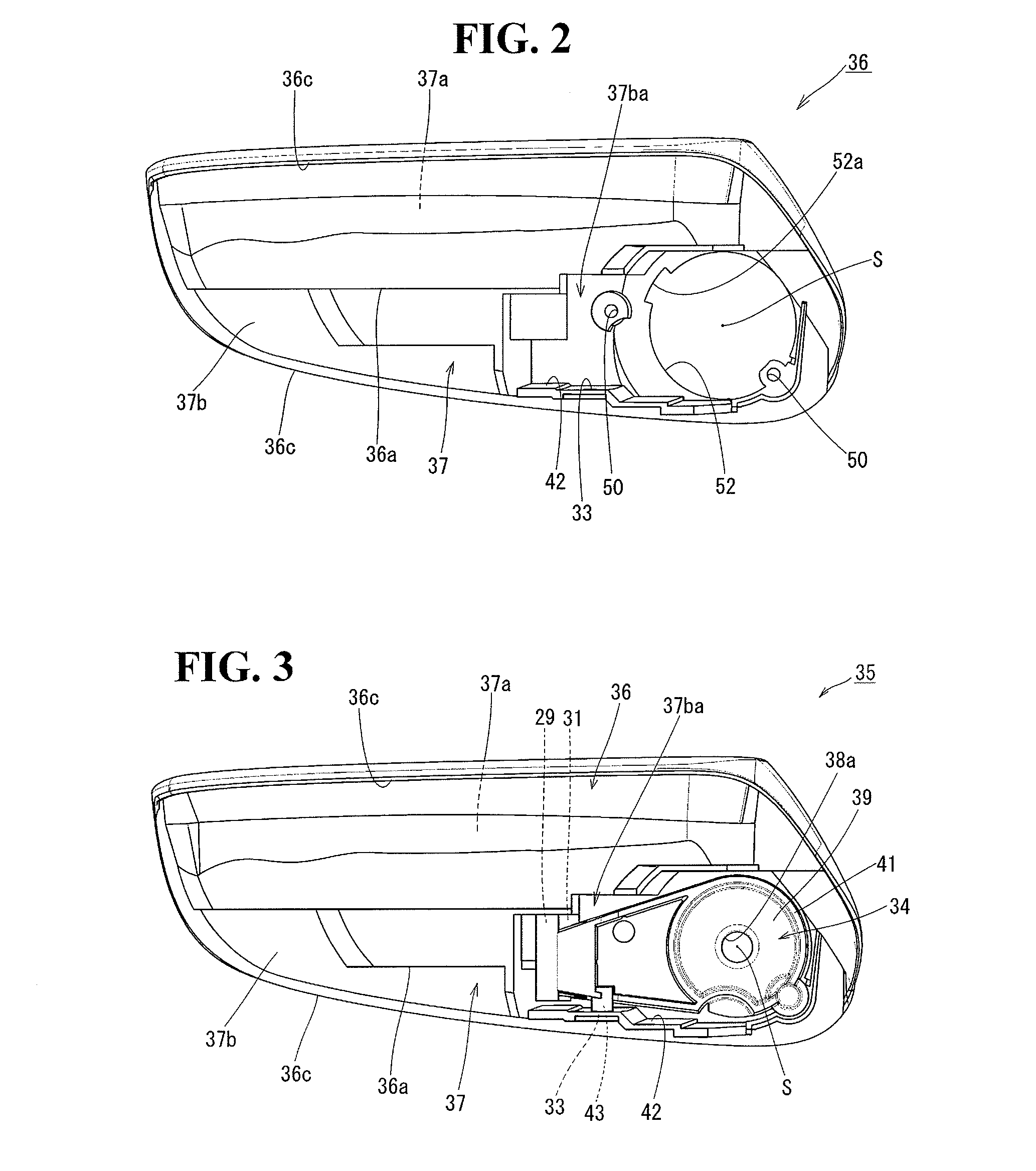
[0061]A third embodiment of a manually retractable door mirror according to the present invention is shown in FIG. 17. Conversely to the first and second embodiments, the annular wall 40 is formed on the side of the base 32 and the annular wall housing groove 58 is formed on the side of the housing support member 34. The rest of the configuration is the same as the first and second embodiments. FIG. 17 is a sectional view taken along a plane passing through the rotation axis S when the housing 36 is at the return position (FIG. 17 corresponds to FIG. 6 according to the first embodiment and FIG. 16 according to the second embodiment). The same components as those in the first and second embodiments are denoted by the same reference numerals as the corresponding components in the first and second embodiments. The annular wall 40 circular in shape is formed on the base 32 coaxially with the rotation axis S, protruding upward. The annular wall housing ...

first embodiment

of Electrically Retractable Door Mirror

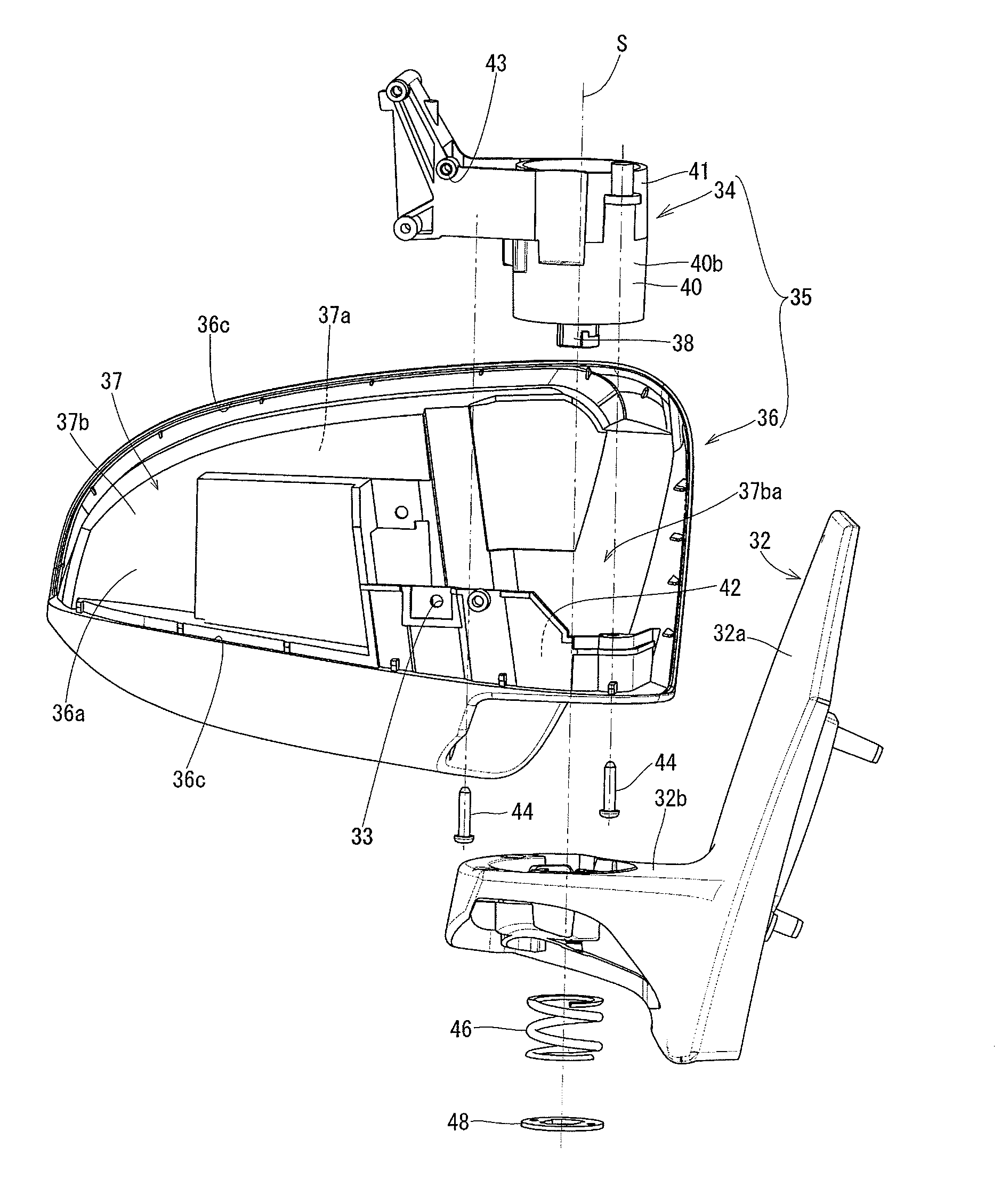
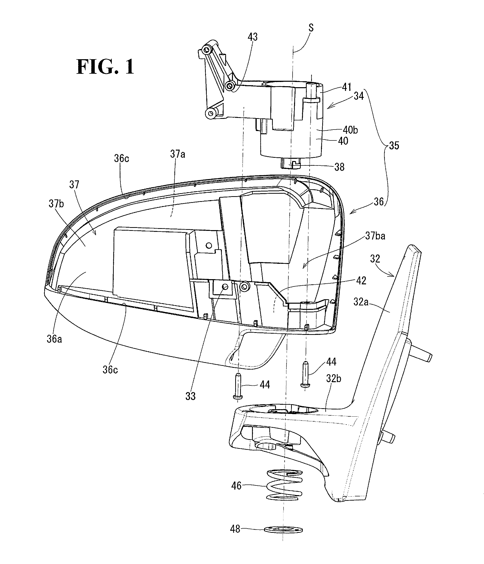
[0063]An First embodiment of an electrically retractable door mirror according to the present invention is shown in FIGS. 18 to 25, where the embodiment is configured using the common base 32 for manually retractable and electrically retractable door mirrors described in the first embodiment of the manually retractable door mirror. The same components as those in the first embodiment of the manually retractable door mirror are denoted by the same reference numerals as the corresponding components in the first embodiment of the manually retractable door mirror. FIG. 18 is an exploded view showing a configuration of the electrically retractable door mirror according to the present embodiment. FIG. 18 shows a right door mirror as viewed from the rear. A housing cover mounted on the rear side of the housing 36, a mirror angle adjustment actuator, a mirror plate, and the like are not shown in FIG. 18. The door mirror includes the base 32 attached to...

second embodiment

of Electrically Retractable Door Mirror

[0079]In the electrically retractable door mirror in FIG. 18, if external shape of the electric drive mechanism 70 and internal shape of the depression 42 are designed such that the electric drive mechanism 70 will be housed and held directly in the depression 42 of the housing 36, the need for the fitting 72 can be eliminated. An embodiment thus configured is shown in FIG. 27. The same components as those in FIG. 18 are denoted by the same reference numerals as the corresponding components in FIG. 18. In FIG. 27, external shape of an electric drive mechanism 70′ and internal shape of a depression 42′ are formed three-dimensionally such that the electric drive mechanism 70′ will be housed and held directly in the depression 42′ of the housing 36. This eliminates the need for the fitting 72 shown in FIG. 18. A part corresponding to the stopper 73a in FIG. 19 is formed on an outer circumferential surface of the electric drive mechanism 70′. Screw...


PUM

PropertyMeasurementUnit
electric drive mechanismaaaaaaaaaa
electric driveaaaaaaaaaa
angleaaaaaaaaaa

Abstract

The present invention provides a door mirror and assembly method therefor with improved assembly performance. A housing support member, housing, and base of a manually retractable door mirror are assembled using screws, a coil spring, and a plate. During assembly, the housing support member is supported in an upside-down position by a jig, and the housing and base are placed in sequence in an upside-down position on the housing support member from above. An electric drive mechanism, fitting, housing, and base of an electrically retractable door mirror are assembled using screws. During assembly, the electric drive mechanism is supported in an upside-down position by a jig, and the fitting, housing, and base are placed in sequence in an upside-down position on the electric drive mechanism from above.

Description

[0001]The disclosure of Japanese Patent Application No. JP2009-281437 filed on Dec. 11, 2009 including the specification, drawings, claims and abstract is incorporated herein by reference in its entirety.BACKGROUND OF THE INVENTION[0002]1. Field of the Invention[0003]The present invention relates to a vehicle door mirror and assembly method therefor with improved assembly performance.[0004]2. Description of the Related Art[0005]A conventional manually retractable vehicle door mirror (hereinafter referred to as a manually retractable door mirror) is described in Japanese Patent Laid-Open No. 7-315128. A conventional electrically retractable vehicle door mirror (hereinafter referred to as an electrically retractable door mirror) is described in Japanese Utility Model Laid-Open No. 6-27337. The manually retractable door mirror described in Japanese Patent Laid-Open No. 7-315128 is assembled as follows: a shaft is assembled onto a frame (housing support member), the assembled structure ...

Claims


Application Information

Patent Timeline
Patent Type & Authority Patents(United States)
IPC IPC(8): B60R1/06G02B7/182
CPCB60R1/074Y10T29/49963Y10T29/49002B60R1/078
Inventor ISEKI, KOTA
Owner MURAKAMI CORP
Why Eureka
Try Eureka