Cord retracting shade operating assembly

a technology of operating assembly and cord, which is applied in the field of cord retracting shade, can solve the problems of free length of cord hanging from the shade, and can present a safety hazard to children and pets

Inactive Publication Date: 2014-10-21
PAGLES JONATHAN R
View PDF6 Cites 2 Cited by
  • Summary
  • Abstract
  • Description
  • Claims
  • Application Information

AI Technical Summary

Benefits of technology

[0005]In view of the foregoing, it is an object of the present invention to provide an improved shade operating assembly. According to an embodiment of the present invention, a shade operating assembly includes a mounting subassembly, and a lift cord subassembly and a lift cord retraction subassembly connected thereto. The lift cord subassembly includes at least one lift cord for effecting movement of a shade by movement of a first end of the at least one lift cord, and a lift cord locking device activatable to selectively engage the at least one lift cord and inhibit further movement thereof. The lift cord retraction subassembly includes a retractor cord engaging the at least one lift cord, and a cord retracting device retracting the retractor cord to retract the first end of the lift cord toward the mounting subassembly.

Problems solved by technology

One well known difficulty associated with such shades concerns the free length of cord hanging from the shade.
In addition to being unsightly, this free length of cord can present a safety hazard for children and pets.

Method used


Image

  • Cord retracting shade operating assembly
  • Cord retracting shade operating assembly
  • Cord retracting shade operating assembly

Examples


Embodiment Construction

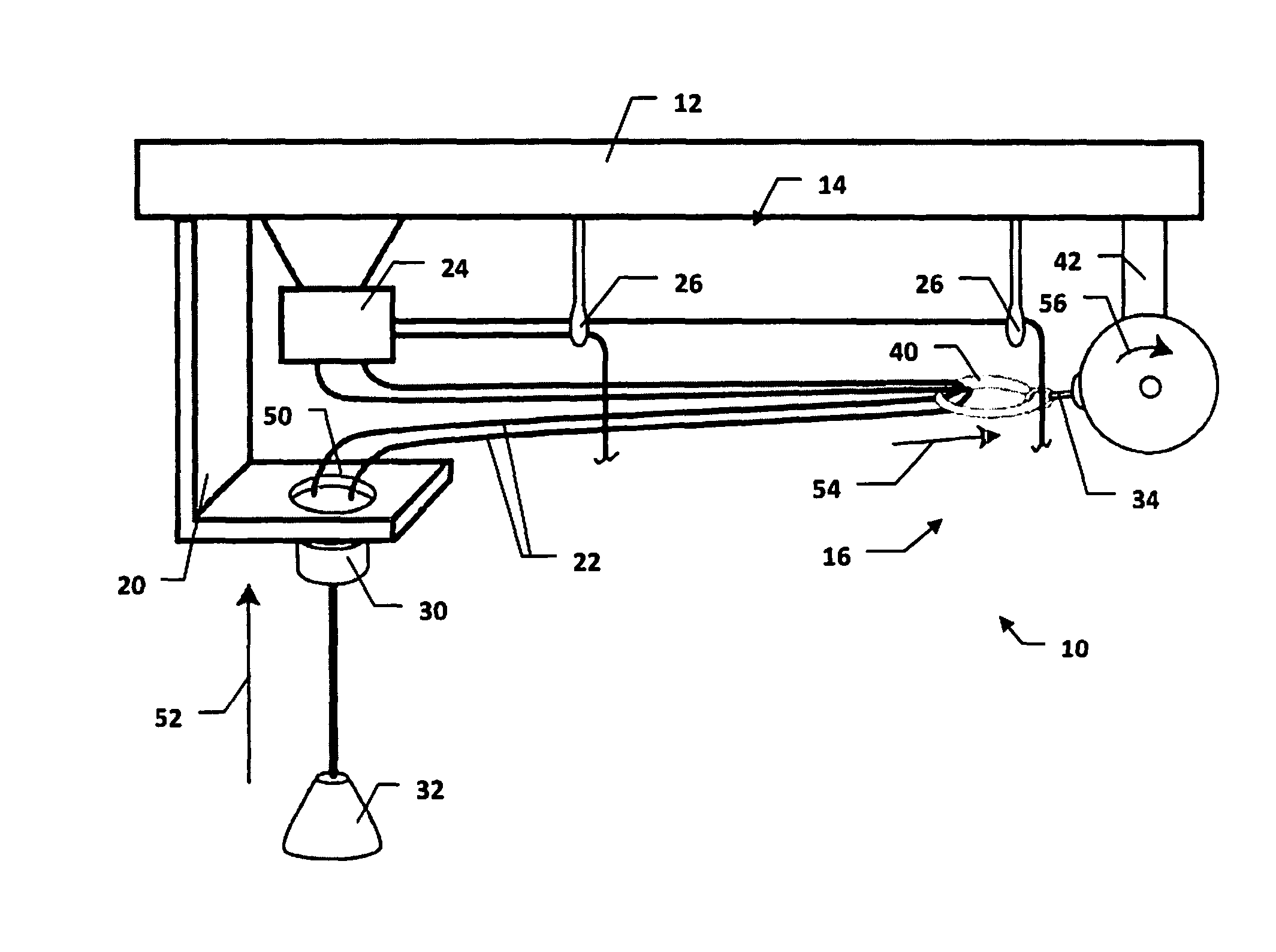
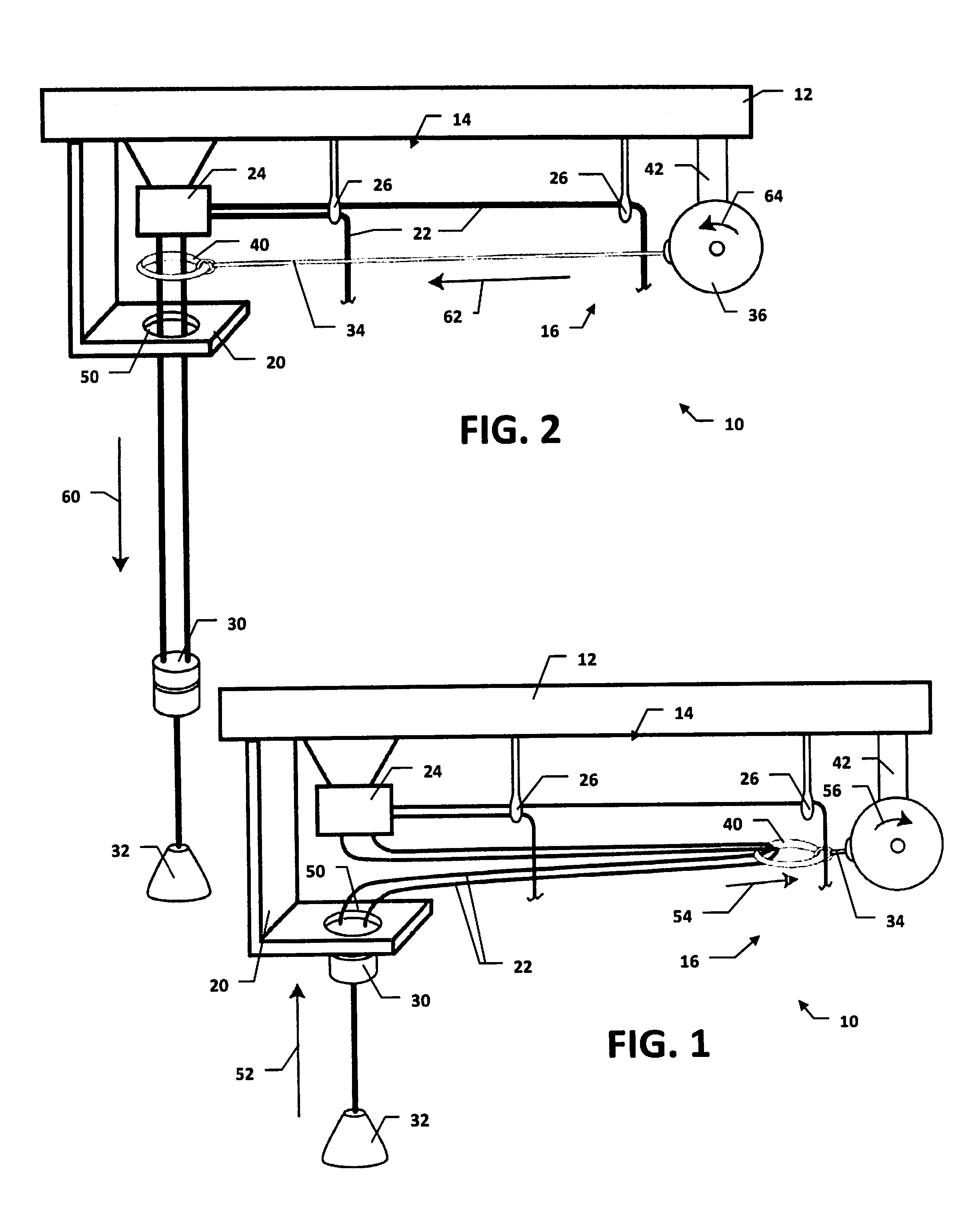
[0024]Referring to FIGS. 1 and 2, a shade operating assembly 10 includes a mounting subassembly 12, a lift cord subassembly 14, a cord retraction subassembly 16 and cord stop bracket 20. The mounting subassembly 12 holds the lift cord and cord retraction subassemblies 14, 16 and the cord stop bracket 20. The lift cord subassembly 14 is operable to move a shade and selectively lock the shade in a plurality of desired positions. The cord retraction subassembly 16 retracts the lift cord subassembly 14, as will be described in greater detail below, with the cord stop bracket 20 limiting retraction.

[0025]The mounting subassembly 12 can also support the shade being operated by the operating assembly 10, or the shade and the operating assembly 10 could use separate mounting components. Preferably, the mounting subassembly 12 includes a unitary head rail, although separate components could be used. In fact, in some embodiments, a window frame or other structural element could serve directly...


PUM


Abstract

A shade operating assembly includes a mounting subassembly, and a lift cord subassembly and a lift cord retraction subassembly connected thereto. The lift cord subassembly includes at least one lift cord for effecting movement of a shade by movement of a first end of the at least one lift cord, and a lift cord locking device activatable to selectively engage the at least one lift cord and inhibit further movement thereof. The lift cord retraction subassembly includes a retractor cord engaging the at least one lift cord, and a cord retracting device retracting the retractor cord to retract the first end of the lift cord toward the mounting subassembly.

Description

CROSS-REFERENCE TO RELATED APPLICATIONS[0001]This application is a continuation-in-part of U.S. Non-Provisional application Ser. No. 13 / 454,078, filed on Apr. 23, 2012, which claims the benefit of U.S. Provisional Application Ser. No. 61 / 478,484, filed on Apr. 23, 2011, the contents of which applications are herein incorporated by reference in their entirety.FIELD OF THE INVENTION[0002]The present invention relates to shades that are moved via cords, and more particularly, to devices and methods for reducing the amount of such cords that hang free when not in use.BACKGROUND OF THE INVENTION[0003]Cord-operated shades, such a roman shades or venetian blinds, are extremely common. For example, many homes will include multiple shades as window treatments, for both functional and aesthetic purposes. The cord operation of such shades, usually to raise or lower them, is a very convenient feature, and the cord mechanism usually incorporate a locking device that is activatable to inhibit fur...

Claims


Application Information

Patent Timeline
Patent Type & Authority Patents(United States)
IPC IPC(8): E06B9/38
CPCE06B9/78E06B9/262
Inventor PAGLES, JONATHAN, R.
Owner PAGLES JONATHAN R
Why Eureka
Try Eureka