
Hearing enhancement system and components thereof

a hearing enhancement and component technology, applied in the field of mixed signal processing, can solve the problems of increasing noise level, unstable noise cancelling circuitry, and insufficient conventional noise cancelling circuitry

Inactive Publication Date: 2013-04-09
SPEAR LABS
View PDF9 Cites 92 Cited by
  • Summary
  • Abstract
  • Description
  • Claims
  • Application Information

AI Technical Summary

Problems solved by technology

While noise cancelling headsets and / or headphones work well in many situations where the noise level is modest (e.g., on an airplane, in a building, etc.), as the noise level increases, the noise cancelling circuitry becomes unstable and may increase the noise level.
For instance, when headsets and / or headphones are used in extremely loud environments (e.g., helicopters, jets, blasting sites (e.g., demolition, military battles, etc.), at a race track, etc.) conventional noise cancelling circuitry is inadequate and a more robust noise cancellation technique is needed.
Even with the more robust noise cancellation circuitry, many persons who are regularly exposed to extremely loud environments experience noise-induced hearing loss.
Another issue for headsets / headphones in loud environments is to allow desired surrounding environmental audio signals to be heard while suppressing the undesired noise.
For instance, a user may be involved in a communication, thus the incoming voice signals are desired and the background noise (e.g., wind, engine noise, etc.) and loud transient noise (e.g., a gun shot, a engine back-firing, etc.) are undesired.
While many headsets / headphones designed for extremely loud environments address one or more of the above issues, they do not address some of the other issues.
For example, a headset / headphone may address the loud background noises but does not handle the loud transient noises well or does not provide an adequate level of hear-through considering the hearing profile of the listener.

Method used


Image

  • Hearing enhancement system and components thereof
  • Hearing enhancement system and components thereof
  • Hearing enhancement system and components thereof

Examples


Embodiment Construction

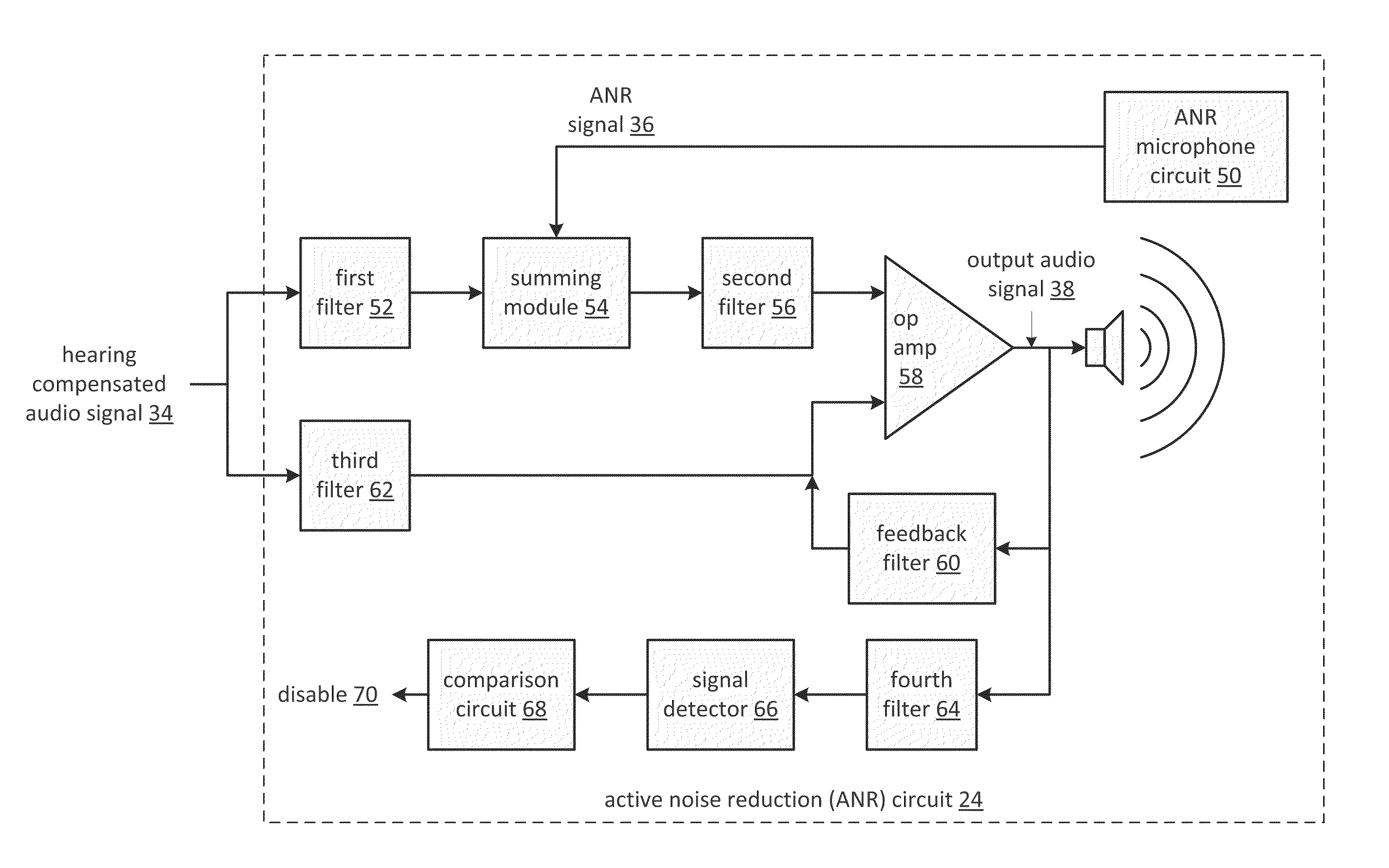
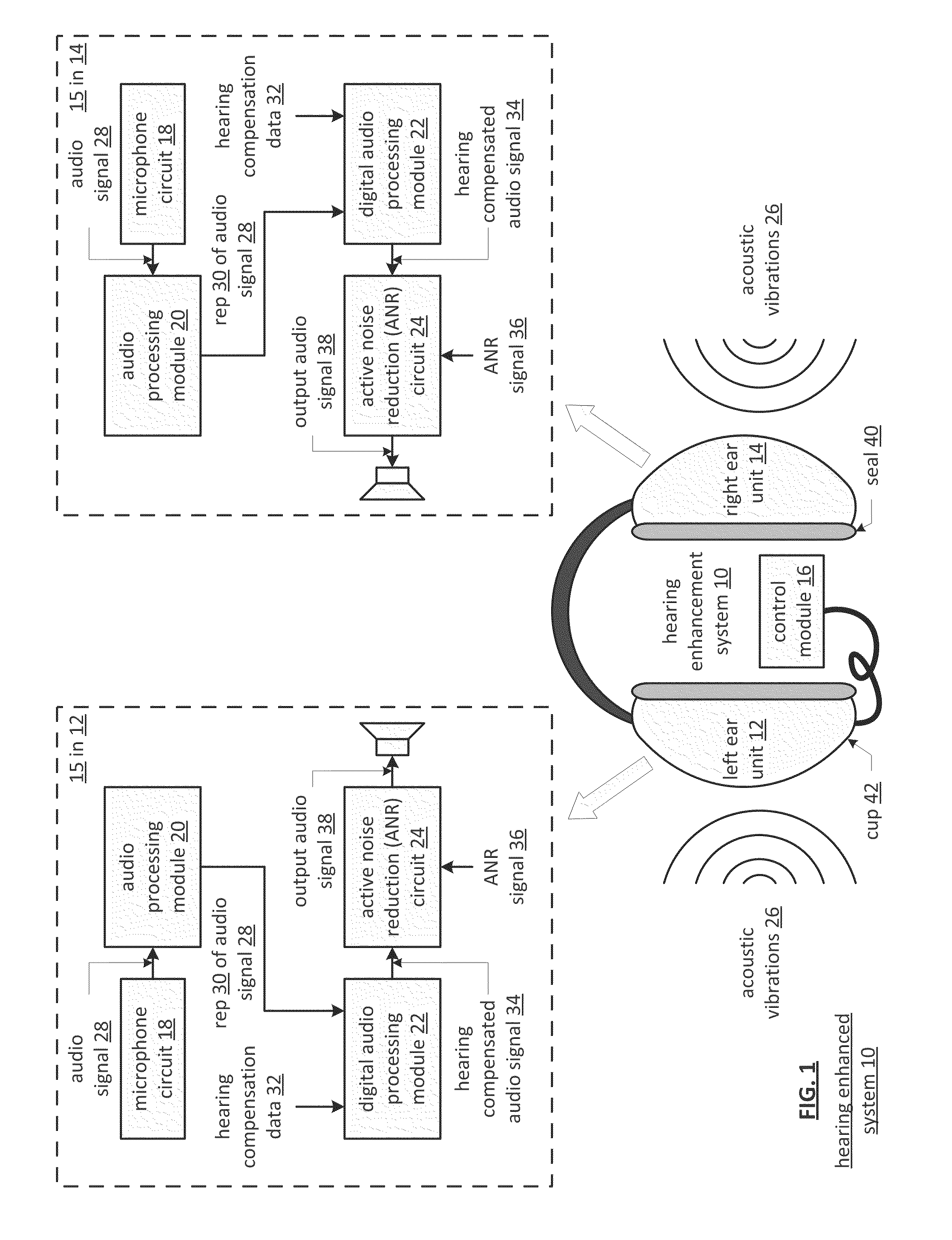
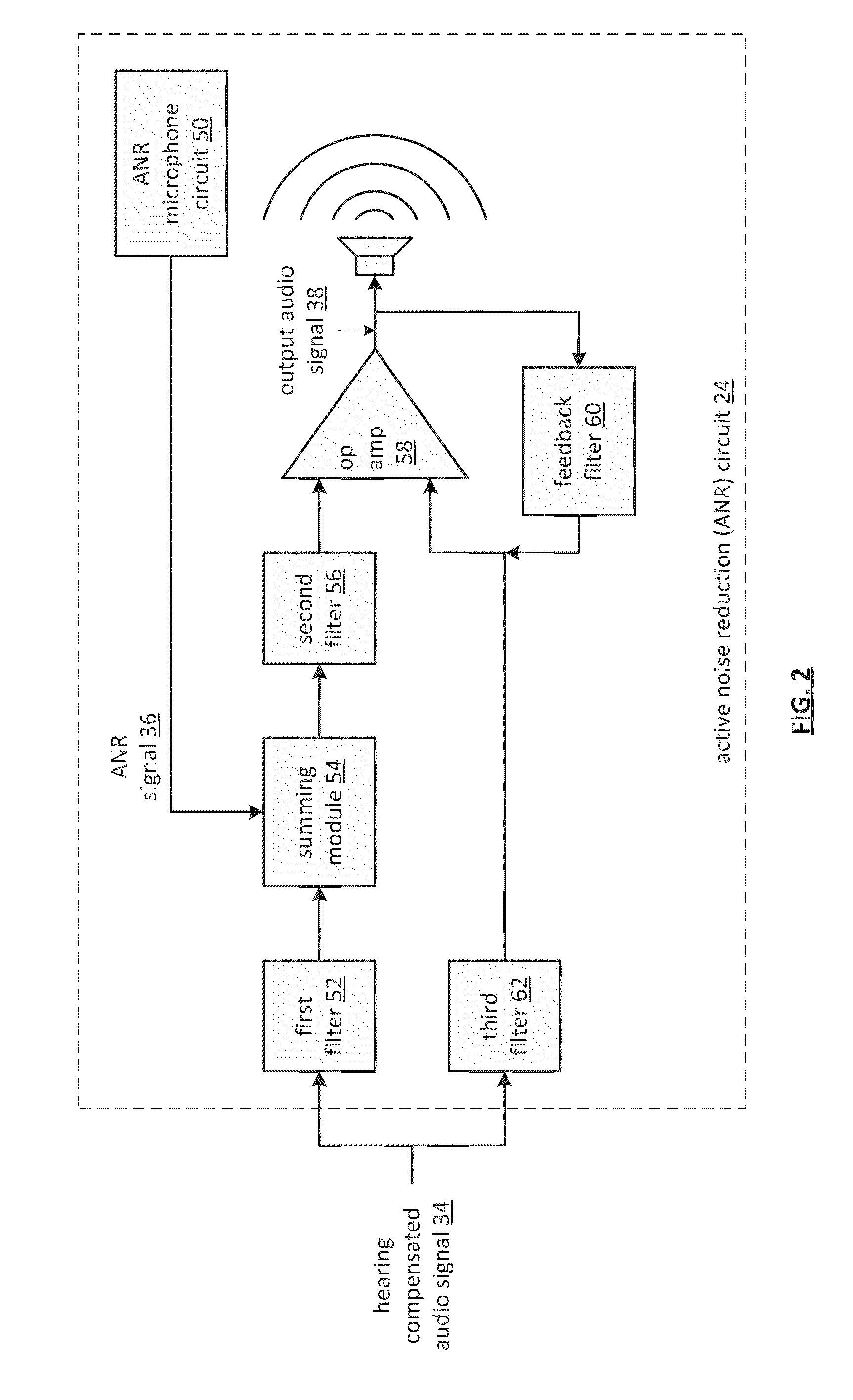
[0023]FIG. 1 is a schematic block diagram of an embodiment of a hearing enhancement system 10 that includes a left ear unit 12, a right ear unit 14, and a control module 16. Each of the left and right ear units 12 and 14 includes a cup housing 42, a circuit 15, and may further include a seal 40. The circuit 15 includes a microphone circuit 18, an audio processing module 20, a digital audio processing module 22, and an active noise reduction (ANR) circuit 24. In this configuration, the hearing enhancement system 10 provides hear-through with reduced localization issues, provides hearing compensation (e.g., hearing aid), and provides active noise reduction for suppressing loud background noises and loud transient noises. As such, the hearing enhancement system 10 is well suited for use in extremely noisy environments.

[0024]The audio processing module 20, and the digital audio processing module 22 may be separate processing modules or may be a shared processing module. The control modu...


PUM


Abstract

A circuit includes a microphone circuit, an audio processing module, a digital audio processing module, and an active noise reduction (ANR) circuit. The microphone circuit receives acoustic vibrations and generates an audio signal therefrom. The audio processing module generates a representation of the audio signal. The digital audio processing module compensates the representation of the audio signal based on hearing compensation data to produce a hearing compensated audio signal. The ANR circuit receives the hearing compensated audio signal and an ANR signal. The ANR circuit further functions to adjust the hearing compensated audio signal based on the ANR signal to produce an output audio signal, wherein the ANR signal is generated based on the output audio signal.

Description

[0001]This patent application is claiming priority under 35 USC §119 to a provisionally filed patent application entitled HEARING ENHANCEMENT SYSTEM AND COMPONENTS THEREOF, having a provisional filing date of Aug. 17, 2009, and a provisional Ser. No. of 61 / 234,598.STATEMENT REGARDING FEDERALLY SPONSORED RESEARCH OR DEVELOPMENT[0002]NOT APPLICABLEINCORPORATION-BY-REFERENCE OF MATERIAL SUBMITTED ON A COMPACT DISC[0003]NOT APPLICABLEBACKGROUND OF THE INVENTION[0004]1. Technical Field of the Invention[0005]This invention relates generally to mixed signal processing and more particularly to audio signal processing.[0006]2. Description of Related Art[0007]Headphones are known to provide an improved listening experience for listening to a variety of audio sources. For example, headphones may be used in commercial settings (e.g., recording studio, audio laboratories, etc.) to listen to audio content (e.g., music, audio signals, voice signals, etc.) with little to no interference from extern...

Claims


Application Information

Patent Timeline
Patent Type & Authority Patents(United States)
IPC IPC(8): G10K11/16
CPCH04R5/033
Inventor LOTT, DALENEWTON, WILLIAM T.
Owner SPEAR LABS
Learn More