Low latency interconnect bus protocol

a low-latency, interconnection bus technology, applied in the direction of connection management, electric digital data processing, instruments, etc., can solve the problems of poor bandwidth utilization, inefficient bandwidth utilization of the bus, and typically very short roundtrip tim

Inactive Publication Date: 2013-04-09
QUALCOMM INC
View PDF16 Cites 18 Cited by
  • Summary
  • Abstract
  • Description
  • Claims
  • Application Information

AI Technical Summary

Benefits of technology

[0020]FIG. 6 is a diagram illustrating the process for establishing a wireless link between components connected using the low latency interconnect bus protocol in accordance with an embodiment of the invention.

Problems solved by technology

Typically, this delay is due to an Acknowledgment (ACK) and flow control update latencies caused by the layers of a PCIe bus.
This results in inefficient bandwidth utilization of the bus as it requires retransmission of packets with no data integrity problem.
That is, a high latency between the PCIe components may cause poor bandwidth utilization.
Thus, the roundtrip time is typically very short and the PCIe is not designed to properly operate in a high latency environment.
However, connectivity of PCIe components over the air would significantly increase the latency of the link, and therefore degrade the performance of the bus.

Method used


Image

  • Low latency interconnect bus protocol
  • Low latency interconnect bus protocol
  • Low latency interconnect bus protocol

Examples


Embodiment Construction

[0021]It is important to note that the embodiments disclosed by the invention are only examples of the many advantageous uses of the innovative teachings herein. In general, statements made in the specification of the present application do not necessarily limit any of the various claimed inventions. Moreover, some statements may apply to some inventive features but not to others. In general, unless otherwise indicated, singular elements may be in plural and vice versa with no loss of generality. In the drawings, like numerals refer to like parts through several views.

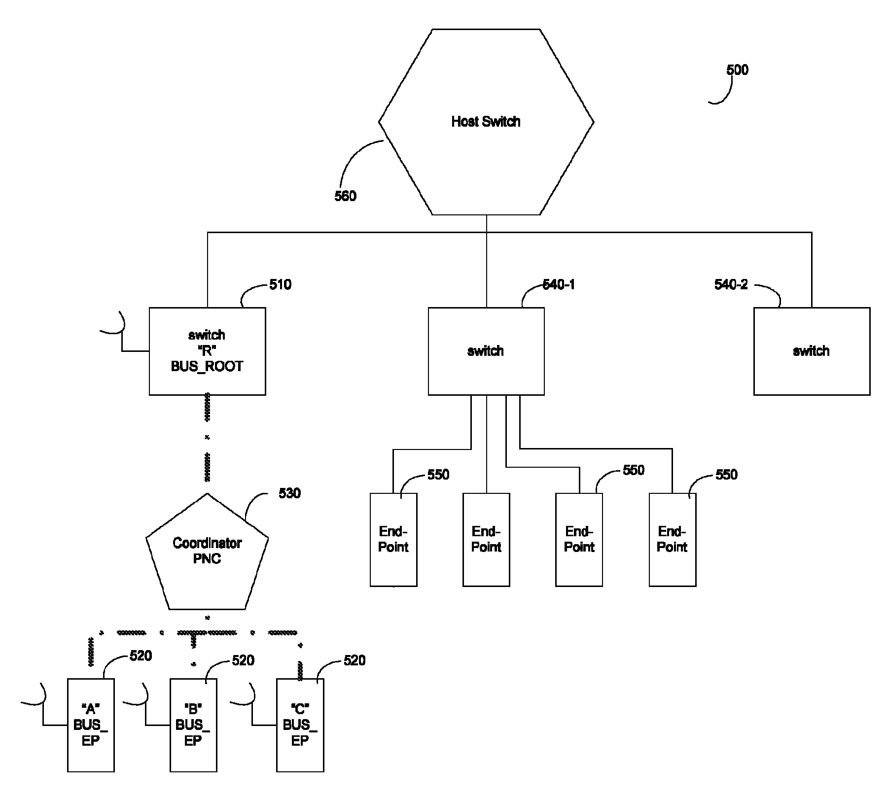
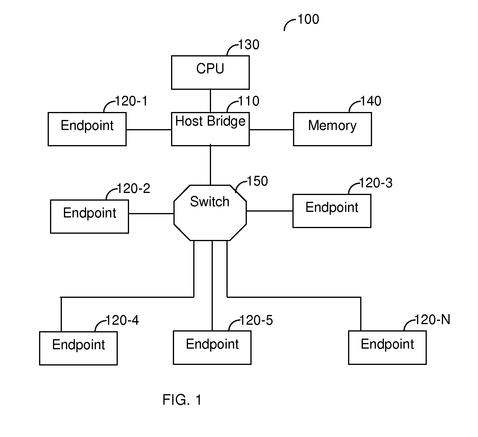
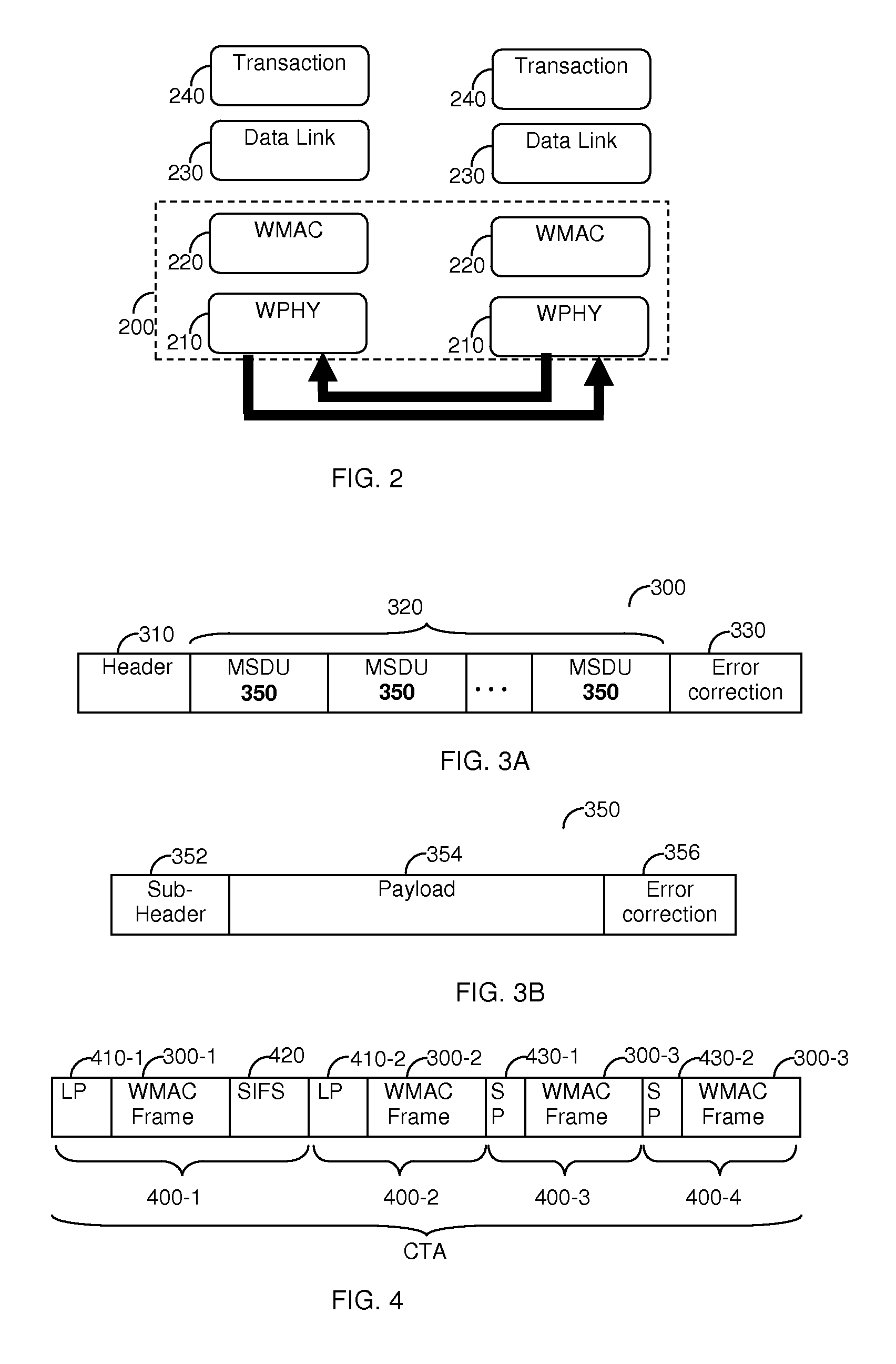
[0022]In accordance with certain embodiments of the invention it is provided a low latency bus protocol, a device and method that enables the connectivity of peripheral devices over a wireless medium. The low latency transmission is realized by modifying the Physical (PHY) layer and Medium Access Control (MAC) layer of a standard wireless communication protocol including, but not limited to, the protocol defined in the...


PUM


Abstract

A device and method for transmitting data over a wireless network, based on a low latency interconnect bus protocol. The low latency interconnect bus protocol is a layered protocol containing a Wireless Medium Access Control (WMAC) layer for constructing a WMAC frame from the data, and a Wireless Physical (WPHY) layer for constructing a WPHY frame from the WMAC frame. The WMAC frame includes an aggregation of a plurality of MAC Service Data Units (MSDUs), and is capable of providing a reliable link by implementing an implied ACK and a block ACK. The WPHY frame is configured to provide a mechanism for a bi-directional communication between components; and the content of the WPHY frame is determined according to a communication state between two communicating components.

Description

CROSS REFERENCE TO RELATED APPLICATIONS[0001]This application claims the benefit of U.S. Provisional Application No. 61 / 028,879 filed on Feb. 14, 2008 and U.S. Provisional Application No. 61 / 091,864 filed Aug. 26, 2008, the contents of which are herein incorporated by reference.FIELD OF THE INVENTION[0002]The present invention relates generally to peripheral component interconnect buses.BACKGROUND OF THE INVENTION[0003]Peripheral component interconnect PCI Express (or “PCIe”) is a high performance, generic and scalable system interconnect bus for a wide variety of applications ranging from personal computers to embedded applications. PCIe implements a serial, full duplex, multi-lane, point-to-point interconnect, packet-based, and switch-based technology. Current versions of PCIe buses allow for a transfer rate of 2.5 Gb / Sec per lane, with a total of 32 lanes.[0004]FIG. 1 shows an illustration of a typical architecture 100 of a computing device that includes a PCIe fabric. A host bri...

Claims


Application Information

Patent Timeline
Patent Type & Authority Patents(United States)
IPC IPC(8): H04J3/16
CPCH04L69/06H04W76/02G06F13/385H04W76/10
Inventor BASSON, GALAZOGUI, TAL
Owner QUALCOMM INC
Why Eureka
Try Eureka