
Mechatronic device

a mechatronic device and electronic technology, applied in the direction of valve operating means/releasing devices, service pipe systems, transportation and packaging, etc., can solve the problems of electrical connections subjected mechanically to inadmissible stress, certain reliability risks, and contacts can be impaired, so as to overcome the disadvantages

Active Publication Date: 2013-04-09
ZF CV SYST EURO BV
View PDF33 Cites 4 Cited by
  • Summary
  • Abstract
  • Description
  • Claims
  • Application Information

AI Technical Summary

Benefits of technology

Enhances operating reliability by reducing mechanical stress on electrical connections, eliminating the need for additional soldering and seals, and improving data transmission resilience against radio interference, particularly in environments prone to electromagnetic interference like motor vehicles.

Problems solved by technology

This conceals certain reliability risks.
As a result, the electrical connections can be subjected mechanically to inadmissible stress.
Consequently, contacts can be impaired by corrosive friction, bond connections can break due to fatigue and soldered junctions can also suffer fatigue, resulting in intermittent contact.
Furthermore, the interface to the pneumatic or hydraulic pressure duct can become prone to leaks.
Moreover, such electrical connections can hinder or complicate the manufacturing process because, for example, an additional soldering process is required.
Also, a mechatronic device, especially if it is installed in a motor vehicle, is often exposed to electrical interference due to ambient radio waves.
This can adversely affect signal transmission.
One such known method involves transponder technology (the use of transponder technology is increasing and, as a result, it can be expected that the cost of the needed modules—transmitter and receiver—will fall).

Method used


Image

  • Mechatronic device
  • Mechatronic device
  • Mechatronic device

Examples


Embodiment Construction

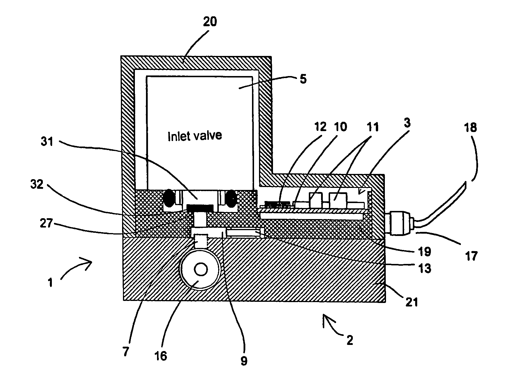
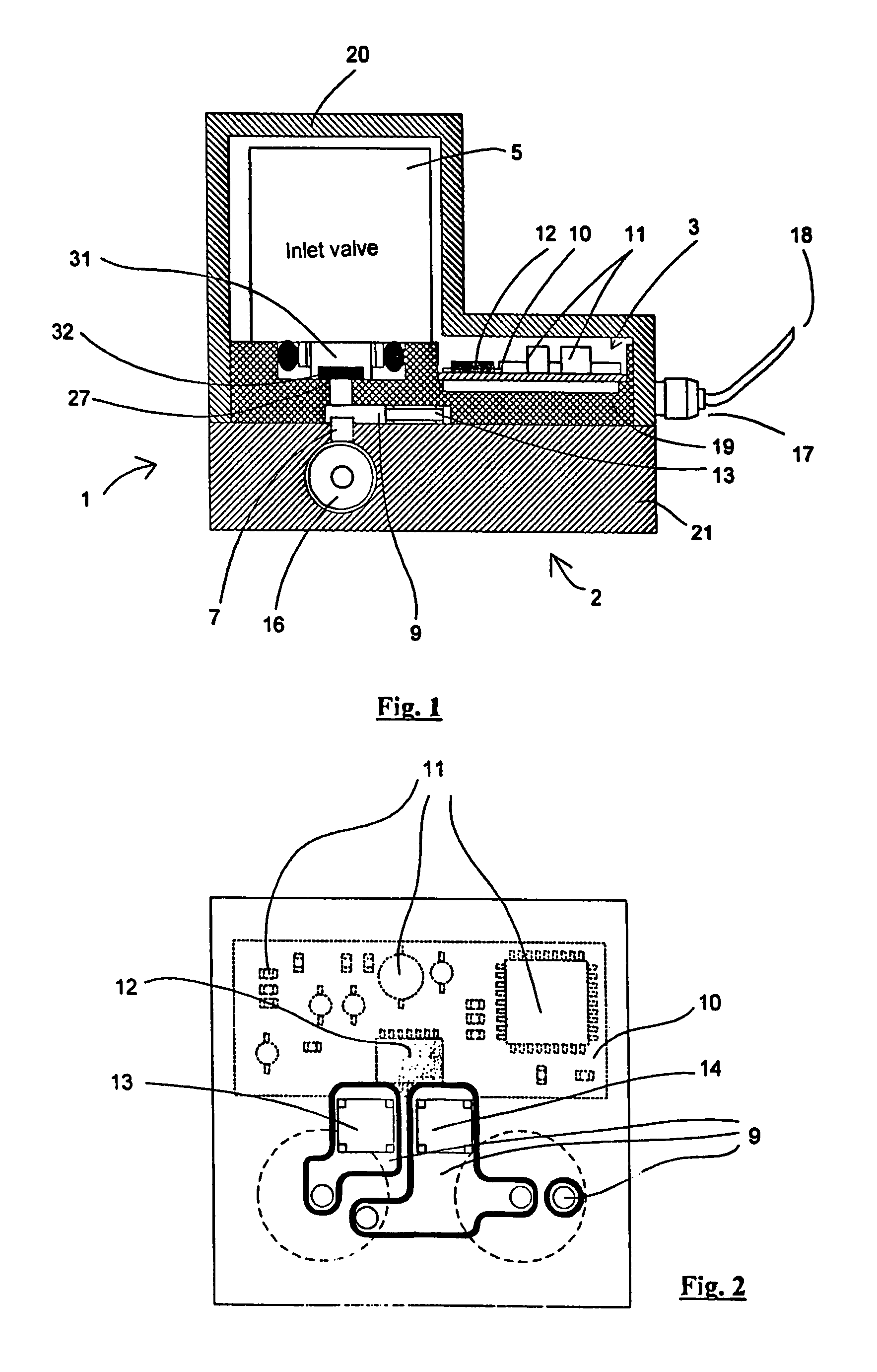
[0042]Referring now to the drawings, where like and corresponding components are represented by like reference numerals, FIG. 1 depicts a mechatronic unit according to an embodiment of the present invention, in this case for operation of a valve array, with a housing (1) having a lower part (21) and a cover (20). The mechatronic device further comprises a mechanical part (2) and an electronic part (3).

[0043]Electronic part (3) can be disposed inside common cover (20). However, it can also be disposed in a separate electronics housing (26) (see FIG. 6), which is mounted on mechanical part (2).

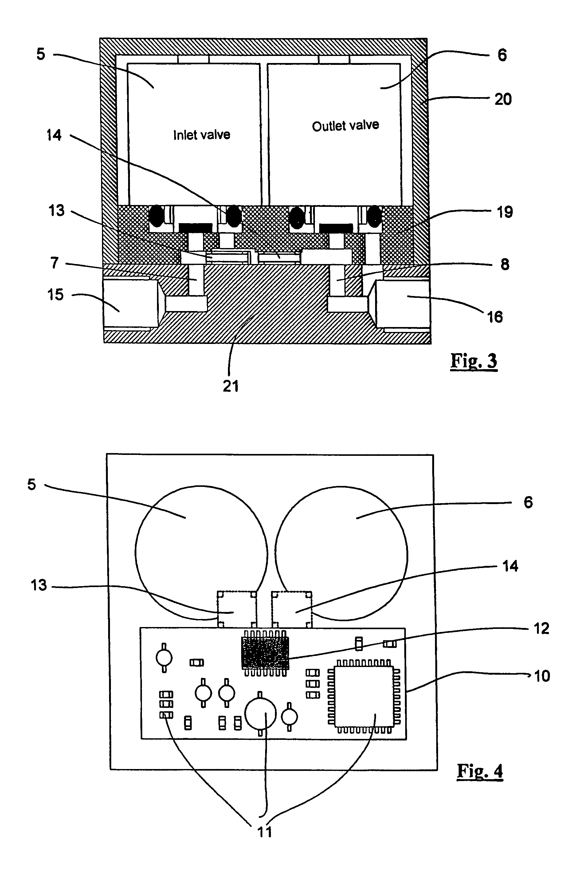
[0044]Under cover (20) there is disposed a solenoid valve pair (5, 6) (see FIG. 3) including an inlet valve (5) and an outlet valve (6). Only the inlet valve (5) is depicted in FIG. 1. A valve-closing element (31) is provided that can close a valve seat (27) by means of a seal (32). As a result, a passage for compressed air or a fluid can be opened and closed.

[0045]To provide a valve connection ...


PUM


Abstract

A mechatronic device comprising a housing that encompasses a mechanical part and an electronic part is provided. The mechanical part includes one or more solenoid valves and pressure-directing ducts. The electronic part includes a printed circuit board with electronic components. Sensor modules are incorporated in the pressure-directing ducts to measure physical parameters. In order to minimize electrical connections and separate seals for the sensor modules, the sensor modules wirelessly communicate with at least one reading station located on the circuit board by means of radio technology or light-emitting and light sensitive elements.

Description

BACKGROUND OF THE INVENTION[0001]The present invention relates to an improved mechatronic device.[0002]Mechatronic devices of the general type under consideration are known. For Example, EP 1 180 602 A1 describes a control-valve device with an electronics box that contains a printed circuit board for mounting electronic components and permits connection to an external bus. One or more solenoid valves can be plugged into the electronics box and thus brought into electrical contact. Electrical control signals arriving from the bus are processed by the electronic unit and distributed to the associated valves. The control-valve device described in EP 1 180 602 A1 does not have any sensors.[0003]DE 100 49 958 A1 describes a fluidic arrangement as well as a valve array and actuator therefor. The associated actuator is provided with a working cylinder with a piston, the position of which can be detected via displacement sensors or limit switches. The output signals of the sensors can be tr...

Claims


Application Information

Patent Timeline
Patent Type & Authority Patents(United States)
IPC IPC(8): E03B7/07
CPCF16H61/0006F15B21/08Y10T137/7761Y10T137/8326
Inventor TEICHMANN, ANDREASAHRENS, KARL
Owner ZF CV SYST EURO BV
Learn More