Methods, systems and/or apparatus relating to inducers for turbine engines

a technology of inducers and turbine engines, which is applied in the direction of liquid fuel engines, vessel construction, marine propulsion, etc., can solve the problems of reducing the relative temperature of flow and making such improvements substantially impossible, and achieve the effect of increasing the cross-sectional area

Active Publication Date: 2013-04-02
GENERAL ELECTRIC CO
View PDF9 Cites 9 Cited by
  • Summary
  • Abstract
  • Description
  • Claims
  • Application Information

AI Technical Summary

Problems solved by technology

In addition, inducers reduce the pressure of the cooling air, which reduces the relative temperature of the flow.
However, conventional inducer design that includes a cylindrical region extending from the throat to the trailing edge, makes such improvements substantially impossible without distorting or causing damage to the optimized geometry of the trailing edge.

Method used


Image

  • Methods, systems and/or apparatus relating to inducers for turbine engines
  • Methods, systems and/or apparatus relating to inducers for turbine engines
  • Methods, systems and/or apparatus relating to inducers for turbine engines

Examples


Embodiment Construction

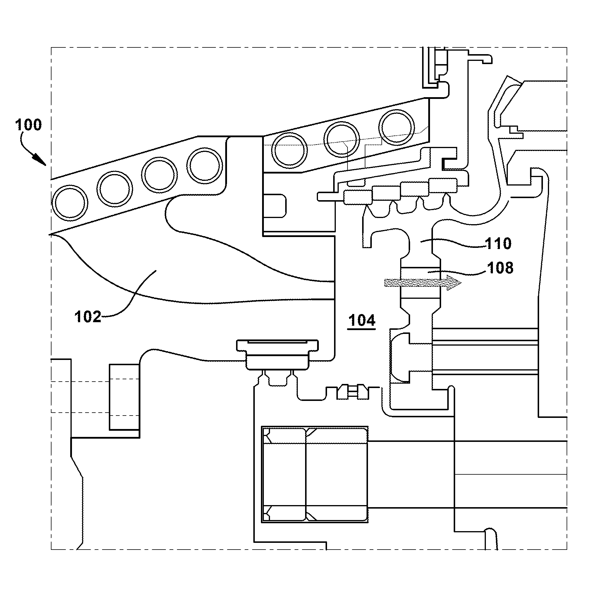
[0012]Referring now to the figures, FIG. 1 illustrates a schematic representation of a section of a gas turbine engine 100. In general, gas turbine engines operate by extracting energy from a pressurized flow of hot gas that is produced by the combustion of a fuel in a stream of compressed air. A gas turbine engine generally is configured with an axial compressor that is mechanically coupled by a common shaft or rotor to a downstream turbine section or turbine, and a combustor positioned between the compressor and the turbine. Note that the following invention may be used in all types of turbine engines, including gas turbine engines, steam turbine engines, aircraft engines, and others. Hereinafter, the invention will be described in relation to a gas turbine engine. This description is exemplary only and not intended to be limiting in any way.

[0013]The compressor generally includes a plurality of axially-stacked stages. Each stage may include a row of compressor rotor blades follow...


PUM


Abstract

An inducer that includes a profiled throat. In some embodiments, the inducer includes a conical shape upstream of the profiled throat with a relatively large circular inlet that narrows to the profiled throat and, downstream of the profiled throat, a downstream section that broadens from the profiled throat. The profiled throat may include an approximate convergent-divergent nozzle geometry.

Description

BACKGROUND OF THE INVENTION[0001]This present application relates generally to methods, systems, and / or apparatus for improving the efficiency and / or operation of turbine engines, which, as used herein and unless specifically stated otherwise, is meant to include all types of turbine or rotary engines, including gas turbine engines, aircraft engines, steam turbine engines, and others. More specifically, but not by way of limitation, the present application relates to methods, systems, and / or apparatus pertaining to improved inducer design for turbine engines.[0002]Gas turbine engines typically include cooling systems that provide cooling air to turbine rotor components, such as turbine blades, in order to limit the temperatures experienced by such components. Prior art cooling systems usually acquire the air used to cool turbine components from the engine's compressor, after which it is diverted and subsequently directed to the turbine section of the engine through an axial passagew...

Claims


Application Information

Patent Timeline
Patent Type & Authority Patents(United States)
IPC IPC(8): F01D9/00
CPCF01D5/081Y02T50/676Y02T50/673F05D2260/97F05D2260/14F01D5/082Y02T50/60F02C7/18F05D2220/32F05D2260/20
Inventor HATMAN, ANCA
Owner GENERAL ELECTRIC CO
Why Eureka
Try Eureka