Energy efficient power steering pump control system

a power steering pump and control system technology, applied in process control, servomotors, instruments, etc., can solve the problems of increasing the torque required to drive the pump, affecting the horsepower output and fuel efficiency of the vehicle, and increasing the pressure on the engine, so as to reduce the fuel consumption, improve the operating efficiency of the motorized vehicle, and minimize the effect of pressur

Active Publication Date: 2013-04-02
FORD GLOBAL TECH LLC
View PDF15 Cites 0 Cited by
  • Summary
  • Abstract
  • Description
  • Claims
  • Application Information

AI Technical Summary

Benefits of technology

[0006]It is an object of the present invention to reduce fuel consumption and improve operating efficiency of a motorized vehicle by minimizing the pressure on the power steering pump, and reducing the consequent torque demanded by the pump when no or relatively low steering assist is required.
[0007]Another object of the present invention is to provide a system that reduces fluid flow to the steering system when little or no steering torque is required. The reduced flow reduces energy losses by reducing the flow circulating through orifice restrictions in the pump and steering system.
[0008]Another object of the present invention is to provide a system that reduces pressures on the supply side of a hydro-mechanical flow control device while maintaining regulated flow.
[0009]A further object of the present invention is to provide a hydro-mechanical flow control device with an electronic pressure control (“EPC”) system that senses fluid pressure output to the steering valve and utilizes input data from the vehicle to determine when and how much of the output flow from the engine driven power steering pump can be directed to the steering valve and / or to the by-pass orifice, and thereby relieve the pump pressure.
[0010]These objects are achieved by a control system for reducing parasitic losses in a power steering system of an automotive vehicle during periods of low demand for power assist and high pump output due to engine speed. A hydraulic pump is driven by the engine or other power source of the vehicle and provides an output of steering fluid to the steering system under pressure. A source of steering fluid is connected to the pump and supplies steering fluid to the pump and receives returned fluid from the power steering and control systems. A hydro-mechanical flow control device, containing a spring biased spool is connected to both the output of the pump and the input to the steering system. The flow control device reacts to predetermined flow and pressure conditions that exist between the output of the pump and the flow and pressure conditions present at the input to the steering system. The flow control device provides a diversion of steering fluid to the source when the pump output pressure is significantly greater than the pressure conditions present at the input to the steering system. The flow control device thus regulates and maintains constant the flow of steering fluid to the steering assist valve as the output of the pump increases or decreases depending on engine rotary speed. The improvement includes the use of an electronic control unit that monitors pressure conditions present at the input to the steering system and other vehicle data signals and then provides override control of the hydro-mechanical flow control device. An electro-hydraulic valve is connected to the supply side of the hydro-mechanical flow control device and reacts to the electronic monitoring of pressure and other vehicle data to alter the counter-balancing forces within the hydro-mechanical flow control device. This causes a by-pass diversion of steering fluid to the source by the hydro-mechanical flow control device and thereby relieves backpressure on the pump when relatively little steering assist is required to be provided by the steering system. The control of steering fluid diversion at such times results in a significant reduction in parasitic losses within the steering system and improves the operating and fuel efficiency of the vehicle.
[0011]In one particular aspect of the invention, an electrically regulated valve is strategically located in parallel with the input to the supply side of a hydro-mechanical flow control device to selectively relieve pressure at the supply side, when desired. When the electric valve is activated, the pressure at the supply side of the spool in the flow control device is reduced and the spool responsively moves towards that lower pressure to open or further open the by-pass orifice. Further opening of the by-pass orifice allows an increase of fluid from the pump to be diverted back to the pump inlet and thereby reduces pump output pressure and flow at the steering valve. Such pressure reduction relieves backpressure on the pumping mechanism of the pump thus reducing the torque on the pump shaft and consequently on torque losses from the engine. The electric valve is electronically controlled according to various inputs selected from the group of data that reflect vehicle speed, steering wheel angle, steering wheel turn rate, steering wheel torque, steering wheel straight ahead position, vehicle lateral acceleration, tie rod force, steering fluid flow rates, and pump output pressure. In this manner, the electrically regulated valve provides enhanced control to the hydro-mechanical flow control device at times when no or relatively low power steering assist is required. Such enhanced control results in a correspondingly regulated by-pass diversion of the pump output that minimizes back pressure on pump and pump driving shaft when no or low steering assist is required. This is achieved independent of the regulation provided by the flow control spool valve during normal vehicle operation when power steering assist is required.

Problems solved by technology

High flow creates higher pressure and increases the torque required to drive the pump.
Such drive torque demand on the engine directly affects vehicle horsepower output and fuel efficiency.

Method used


Image

  • Energy efficient power steering pump control system
  • Energy efficient power steering pump control system
  • Energy efficient power steering pump control system

Examples


Embodiment Construction

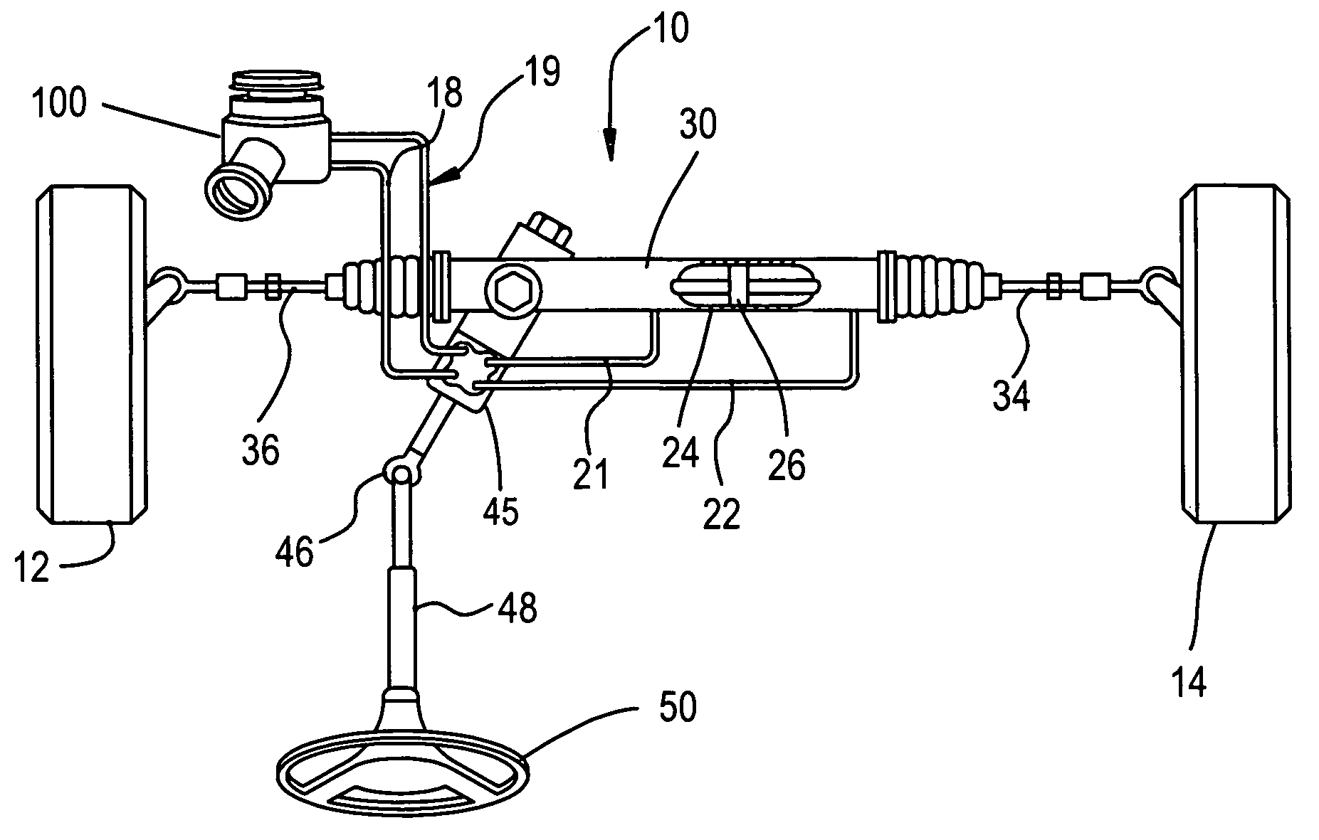
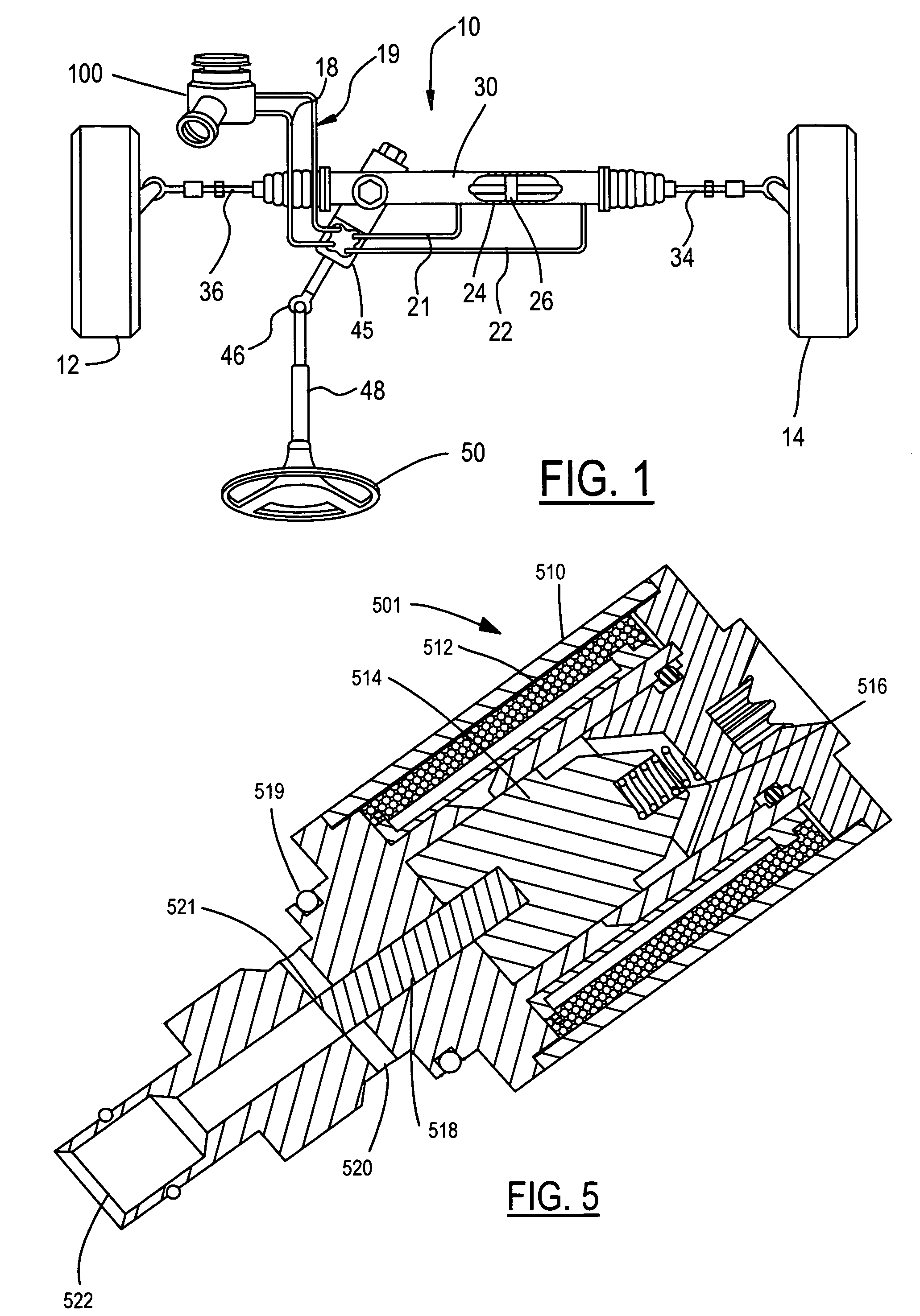
[0018]FIG. 1 illustrates a conventional power steering system 10, as is typically employed in an automotive vehicle. Steering system 10 includes a steering gear 24 and a hydraulic assist piston 26 in a housing 30. (Many possible steering mechanisms, such as, but not limited to, rack and pinion, re-circulating-ball, or worm-roller mechanisms may be used.) A steering wheel 50 is shown connected to a steering column 48 and, through a rotating universal joint 46, to steering assist valve 45. Tie rods 34 and 36 extend from steering gear 24 and provide the interconnection between the steering gear 24 and wheels 12 and 14, which are mounted to the vehicle chassis (not shown). An engine driven pump assembly and reservoir 100 provides power steering hydraulic fluid under pressure through an outlet line 18 to torque driven steering assist valve 45. A portion of the pumped fluid is supplied from steering assist valve 45 to the steering gear through output lines 21 and 22. This pressurized flui...


PUM


Abstract

An electronic control unit monitors pressure conditions present at the input to the steering system and other vehicle data signals and then provides override control of a hydro-mechanical flow control device. An electro-hydraulic valve is connected to the supply side of the hydro-mechanical flow control device and reacts to the electronic monitoring of pressure and other vehicle data to alter the counter-balancing forces within the hydro-mechanical flow control device. This causes a by-pass diversion of steering fluid to the source by the hydro-mechanical flow control device and thereby relieves backpressure on the pump when relatively little steering assist is required to be provided by the steering system. The control of steering fluid diversion at such times results in a significant reduction in parasitic losses within the steering system and improves the operating and fuel efficiency of the vehicle.

Description

BACKGROUND[0001]1. Field of the Invention[0002]The invention relates to the field of power steering pumps as used in automotive vehicles and more specifically to the area of improved energy efficiencies in flow control devices that are used to control the delivery of hydraulic fluid to steering assist valves.[0003]2. Description of the Prior Art[0004]In conventional power assist steering systems, many techniques are used to position the location of a spool within a control valve to regulate the delivery of a constant amount of hydraulic fluid from a pump to a steering assist valve. Because the flow from the pump increases or decreases depending on the pump rotary speed, the flow regulation mechanism of the control valve is necessary to maintain a constant flow to the steering assist valve independent of pump rotary speed. In most cases, a by-pass orifice is established in the control valve that allows excess steering fluid to be diverted back to the pump input port or a fluid source...

Claims


Application Information

Patent Timeline
Patent Type & Authority Patents(United States)
IPC IPC(8): B62D5/065
CPCB62D5/065Y10T137/2607
Inventor KASTEN, FREDERICK R.RECKER, DARREL A.TUTTLE, DANIEL K.ZEID, ASHRAF
Owner FORD GLOBAL TECH LLC
Why Eureka
Try Eureka