Electronic apparatus and disk drive suspension
a technology of electronic equipment and disk drive, which is applied in the field of electronic equipment, can solve the problems of poor adhesion to the conductive resin, inability to reduce the electrical resistance between the conductive resin and the conductive plate member, and inability to reduce the electrical resistance between the conductive resin and the conductive plate member, and achieve the effect of reliable electrical conduction
- Summary
- Abstract
- Description
- Claims
- Application Information
AI Technical Summary
Benefits of technology
Problems solved by technology
Method used
Image
Examples
first embodiment
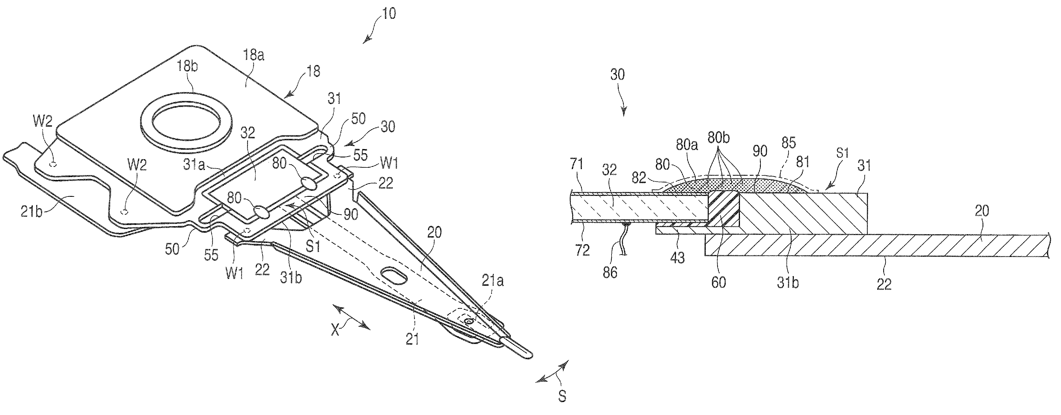
[0027]A disk drive suspension according to the present invention will now be described with reference to FIGS. 1 to 6.
[0028]A disk drive (HDD) 1 shown in FIG. 1 comprises a case 2, spindle 3, disks 4 rotatable about the spindle 3, carriage 6 turnable about a pivot 5, positioning motor (voice coil motor) 7 for actuating the carriage 6, etc. The case 2 is covered by a lid (not shown).
[0029]FIG. 2 is a sectional view typically showing a part of the disk drive 1. As shown in FIG. 2, the carriage 6 comprises arms (carriage arms) 8. A suspension 10 is mounted on the distal end portion of each arm 8. A slider 11, which constitutes a magnetic head, is disposed on the distal end portion of the suspension 10. When each disk 4 is rotated at high speed, an air bearing is formed between the disk 4 and the slider 11.
[0030]If the carriage 6 is turned by the positioning motor 7, the suspension 10 moves radially relative to the disk 4. Thereupon, the slider 11 moves to a desired track of the disk 4....
second embodiment
[0062]FIG. 7 shows a suspension 10A with a microactuator mounting section 30A according to a The mounting section 30A comprises a pair of microactuator elements 32a and 32b. An extended portion 100 is formed on a conductive plate member 31A that also serves as a baseplate. A movable part 31b is disposed on the distal end of the extended portion 100. The microactuator elements 32a and 32b are arranged parallel to each other between a stationary part 31a and the movable part 31b of the conductive plate member 31A.
[0063]In this suspension 10A, a boss portion 18b is formed by pressing the conductive plate member 31A that doubles as the baseplate. The boss portion 18b is secured to its corresponding arm 8 of the carriage 6 of the disk drive 1 (FIGS. 1 and 2). A thin porous gold plating layer 90 is formed on the entire outer surface of the conductive plate member 31A. The outer surface of the conductive plate member 31A includes region S2 in which the conductive resin members 80 are arra...
PUM
| Property | Measurement | Unit |
|---|---|---|
| thickness | aaaaa | aaaaa |
| thickness | aaaaa | aaaaa |
| thick | aaaaa | aaaaa |
Abstract
Description
Claims
Application Information
 - R&D
- Intellectual Property
- Life Sciences
- Materials
- Tech Scout
- Unparalleled Data Quality
- Higher Quality Content
- 60% Fewer Hallucinations
Browse by: Latest US Patents, China's latest patents, Technical Efficacy Thesaurus, Application Domain, Technology Topic, Popular Technical Reports.
© 2025 PatSnap. All rights reserved.Legal|Privacy policy|Modern Slavery Act Transparency Statement|Sitemap|About US| Contact US: help@patsnap.com


