Actuator
a technology of actuators and actuators, applied in piezoelectric/electrostrictive/magnetostrictive devices, piezoelectric/electrostriction/magnetostriction machines, basic electric elements, etc., can solve problems such as poor portability, increased size and weight, and durability problems, and achieve high durability and reduce size and weight
- Summary
- Abstract
- Description
- Claims
- Application Information
AI Technical Summary
Benefits of technology
Problems solved by technology
Method used
Image
Examples
first embodiment
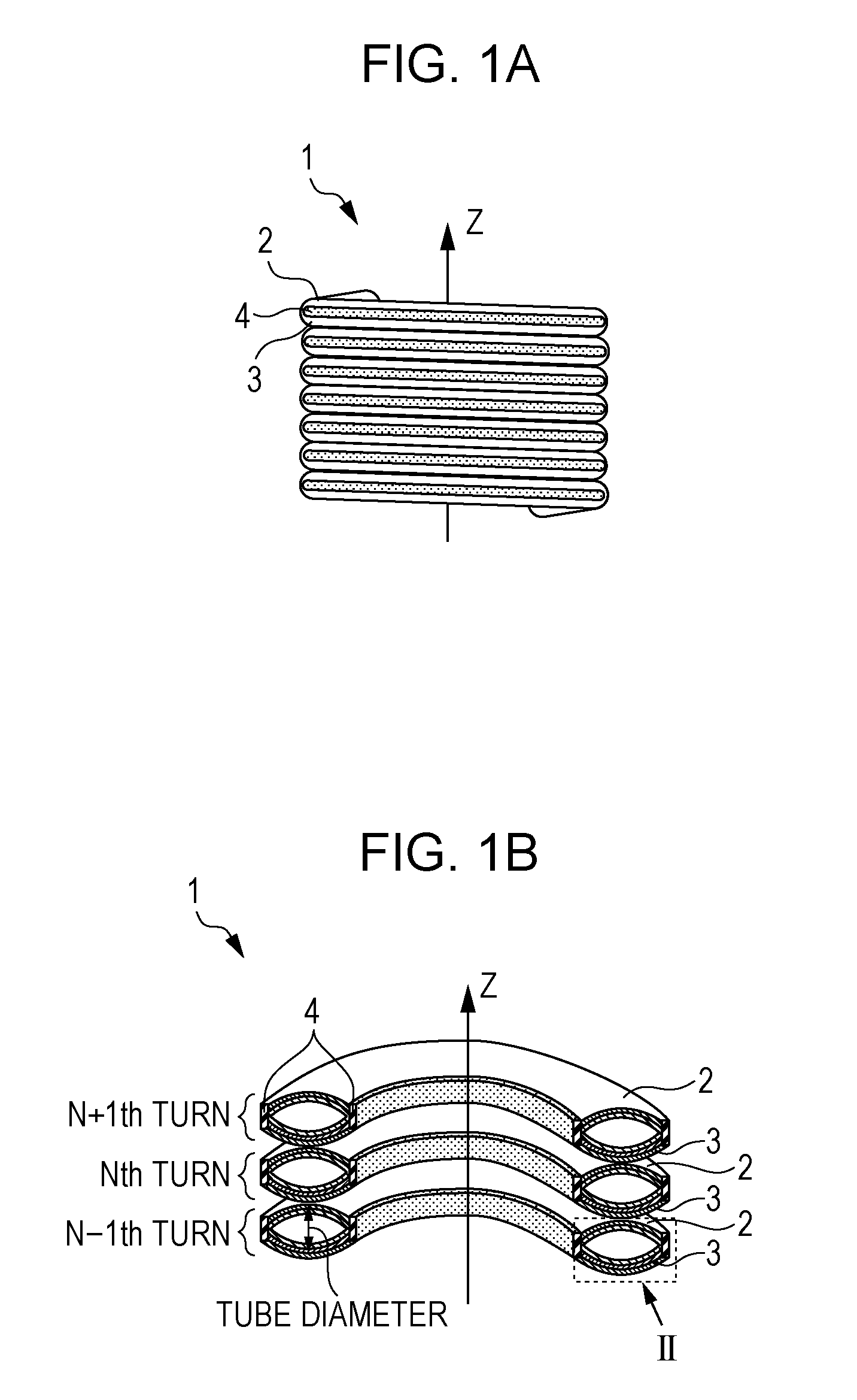
[0025]The spiral composite actuator 1 according to a first embodiment of the invention has a structure in which the long sides of each of the two long actuator portions 2 and 3 are connected through connection members 4 as illustrated in FIGS. 1A and 1B. The spiral composite actuator 1 has a structure in which the long actuator portions 2 and 3 with the connection members are wound around the screw axis Z. In the long actuator portions 2 and 3 connected to each other at both ends of the long sides, portions other than the connection members are not connected to each other, and thus a hollow structure can be formed as in a tube.
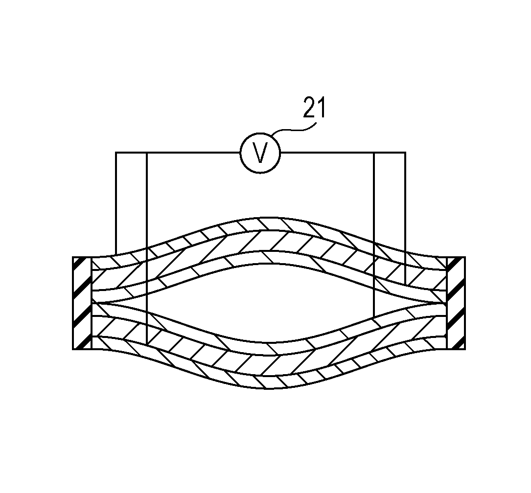
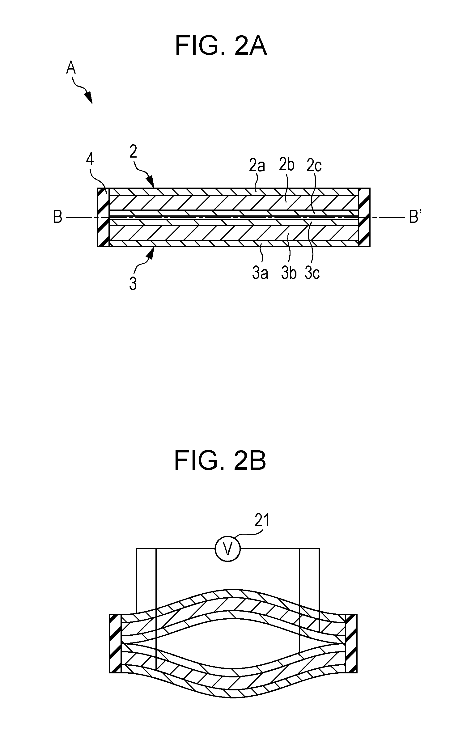
[0026]By applying electrical energy to the long actuator portions 2 and 3 in such a manner as to bend in opposite directions to each other, the long actuator portions 2 and 3 mutually bend in the direction of changing the diameter of the hollow portion, i.e., in such a manner as to change the maximum distance therebetween. Due to the fact that the bending move...
second embodiment
[0102]As a modification of the first embodiment, a spiral composite actuator 1 can also be formed by winding the facing surface of each unit in the direction along the screw axis Z, i.e., the direction in parallel to the screw axis.
[0103]FIG. 5 illustrates a portion corresponding to two turns of the turns of the spiral among the cross sectional views obtained by cutting the spiral composite actuator 1 at the plane including the screw axis Z. FIG. 5A illustrates the state before voltage application and FIG. 5B illustrates the state in voltage application when the facing surface of each unit is wound around the screw axis. More specifically, the facing surface of each unit has a region that spreads always in the direction perpendicular to the screw axis.
[0104]As illustrated in FIGS. 5A and 5B, the spiral composite actuator 1 changes the tube diameter of the spiral by the changes in the distance between the long actuator portions 2 and 3 in response to voltage application. Due to the f...
third embodiment
[0114]This embodiment is a modification of the first embodiment and has a structure in which the long actuator portions 2 and 3 are divided at arbitrary positions.
[0115]FIG. 6 illustrates a unit of the long actuator portions and is a view illustrating the cross sectional region II illustrated in FIG. 1B and a portion continuous therefrom in the longitudinal direction.
[0116]In each of the long actuator portions 2 and 3, one or more slits 15 are formed at facing positions and divided. Here, the slits 15 refer to notches formed in the electrode layers and the long electrolyte layer constituting the long actuator portions and the three layers may be collectively cut or notches may formed only in the electrode layers. The ease of bending of a film depends on the cross sectional shape and a film having a smaller slit width is easily bended. Therefore, it is suitable to collectively cut the three layers. The width of the slits is arbitrarily determined. However, the slits become dead space...
PUM
 Abstract
Description
Claims
Application Information
 - R&D
- Intellectual Property
- Life Sciences
- Materials
- Tech Scout
- Unparalleled Data Quality
- Higher Quality Content
- 60% Fewer Hallucinations
Browse by: Latest US Patents, China's latest patents, Technical Efficacy Thesaurus, Application Domain, Technology Topic, Popular Technical Reports.
© 2025 PatSnap. All rights reserved.Legal|Privacy policy|Modern Slavery Act Transparency Statement|Sitemap|About US| Contact US: help@patsnap.com


