
Sensor element and method for operating a sensor element

a sensor element and sensor technology, applied in the direction of speed/acceleration/shock measurement, measurement devices, instruments, etc., can solve the problem that the excitation element cannot be provided between the seismic mass and the substrate, and achieve the reduction of wiring complexity, small installation space, and simplified evaluation of the second deflection.

Active Publication Date: 2013-03-26
ROBERT BOSCH GMBH
View PDF9 Cites 1 Cited by
  • Summary
  • Abstract
  • Description
  • Claims
  • Application Information

AI Technical Summary

Benefits of technology

The sensor element described in this patent allows for detection of acceleration forces in two directions, making it suitable for a variety of applications. The element requires less installation space, simplifies evaluation of second deflection, reduces wiring complexity, and enables a multichannel sensor to be implemented. The detecting element measures changes in electrical capacitance caused by the deflection of a seismic mass, which is predeflected in a perpendicular direction to the main extension plane. This predeflection allows the detecting element to distinguish between a second deflection oriented in the direction of the substrate and a second deflection oriented away from the substrate in the third direction. The sensor element also measures the first and second electrical capacitances between a comb electrode and a counter-electrode, which change as the overlapping area between them changes. This allows for detection of the intensity and direction of acceleration in the third direction.

Problems solved by technology

Furthermore, an excitation element is not provided between the seismic mass and the substrate.

Method used


Image

  • Sensor element and method for operating a sensor element
  • Sensor element and method for operating a sensor element
  • Sensor element and method for operating a sensor element

Examples


Embodiment Construction

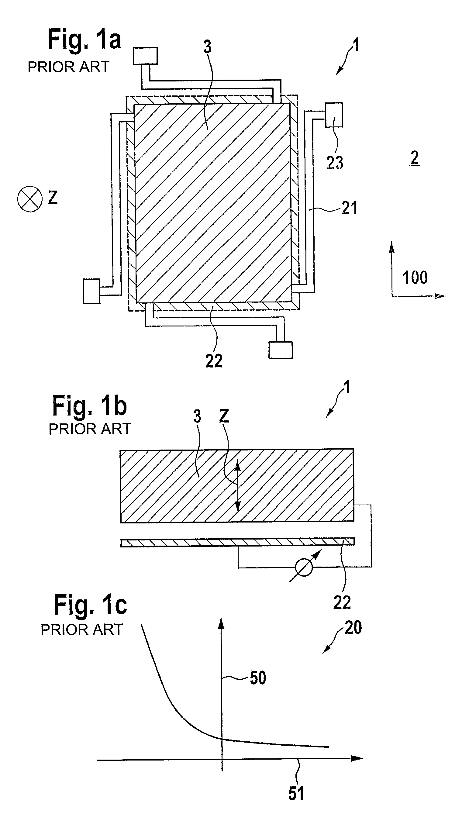
[0016]FIGS. 1 a, 1 b and 1 c show schematic views of a sensor element 1 and a schematic capacitance curve 20 for a sensor element 1 according to the related art, sensor element 1 including a substrate 2 and a seismic mass 3 which is movable relative to substrate 2. Seismic mass 3 is attached to substrate 2 with the aid of four spiral springs 21 via anchoring elements 23 in such a way that an elastic second deflection of seismic mass 3 relative to substrate 2 along a third direction Z perpendicular to a main extension plane 100 of substrate 2 is made possible. A detecting electrode 22 is also situated between substrate 2 and seismic mass 3. Electrical voltage 24 between seismic mass 3 and detecting electrode 22 is dependent on the electrical capacitance between seismic mass 3 and detecting electrode 22, which in turn, is dependent on the distance between seismic mass 3 and detecting electrode 22 along third direction Z. The measurement of the electrical capacitance is thus a measure ...


PUM


Abstract

A sensor element, in particular a multichannel acceleration sensor having a substrate and a seismic mass, the sensor element having a detecting element for detecting a deflection of the seismic mass relative to the substrate, and the sensor element having an excitation element for exciting a deflection of the seismic mass perpendicular to the main extension plane.

Description

BACKGROUND INFORMATION[0001]Sensor elements are generally known. For example, an acceleration sensor, which has a seismic mass which is movably suspended on a substrate and is deflectable in a direction parallel to the substrate via external acceleration forces, and has evaluation means for detecting an acceleration-induced deflection of the seismic mass parallel to the substrate, is described in German Patent No. DE 197 19 779. Furthermore, an acceleration sensor, which includes a seismic mass designed in the form of an asymmetrical rocker structure for detecting acceleration effects perpendicular to the substrate, is described in German Patent No. DE 10 2007 048 882. Detection of acceleration forces which act upon the seismic mass both perpendicular and parallel to the substrate with the aid of only a single acceleration sensor is not provided for. Furthermore, an excitation element is not provided between the seismic mass and the substrate.SUMMARY OF THE INVENTION[0002]The sensor...

Claims


Application Information

Patent Timeline
Patent Type & Authority Patents(United States)
IPC IPC(8): G01P15/125G01P15/18
CPCG01P15/125G01P15/18G01P2015/0814
Inventor STAHL, HEIKOGROSSE, AXEL
Owner ROBERT BOSCH GMBH
Learn More