
Broadband high dynamic range digital receiving system for electromagnetic signals

a digital receiving system and electromagnetic signal technology, applied in the direction of diversity/multi-antenna system, transmission monitoring, polarisation/directional diversity, etc., can solve the problems of limited use of adcs as rf-to-digital converters in wideband software-defined radio applications, comparatively expensive system incorporating limited-use components, and the dynamic range performance of commercial adcs increases at a slower ra

Active Publication Date: 2013-03-19
THE UNITED STATES OF AMERICA AS REPRESENTED BY THE SECRETARY OF THE NAVY
View PDF13 Cites 6 Cited by
  • Summary
  • Abstract
  • Description
  • Claims
  • Application Information

AI Technical Summary

Benefits of technology

The patent describes a method for a wideband signal receiving system that uses an analog-to-digital (ADC) boundary close to the air interface to capture all radio signals. This positioning reduces the cost and complexity of the system and increases the signal dynamic range above the boundary of the available ADC technology. The method also teaches that existing systems can be improved by using available ADCs in most wideband applications, as long as the signal levels do not exceed the maximum signal levels that can be processed by the available ADCs.

Problems solved by technology

ADCs are limited to be used as RF-to-Digital converters in wideband software-defined radio applications.
In either case, the result is a comparatively costly system incorporating limited-use components.
However, the dynamic-range performance of commercial ADCs increases at a slower rate because the bulk of commercial applications can be met with current technology.

Method used


Image

  • Broadband high dynamic range digital receiving system for electromagnetic signals
  • Broadband high dynamic range digital receiving system for electromagnetic signals
  • Broadband high dynamic range digital receiving system for electromagnetic signals

Examples


Embodiment Construction

1) Operating Frequency and Instantaneous Bandwidth

[0036]In the present invention, an instantaneous signal bandwidth is chosen that is less than or equal to one-half of the analog-to-digital converter (ADC) sampling frequency, the bandwidth being known as the Nyquist bandwidth (the background “Nyquist” theorem is well-known to those ordinarily skilled in the art). The detection bandwidth is typically much smaller than the instantaneous bandwidth and is the minimum bandwidth associated with the minimum detectable signal (MDS). The MDS is equal to the system noise power in the detection bandwidth.

[0037]An ADC frequency response band comprises a plurality of equal bandwidth contiguous Nyquist zones that form a continuous frequency band from zero frequency to multiples of the sampling frequency. A signal entering the ADC process in any one of these Nyquist bands is aliased to all other Nyquist bands by the sampling process. The aliasing process is well known to those ordinarily skilled i...


PUM


Abstract

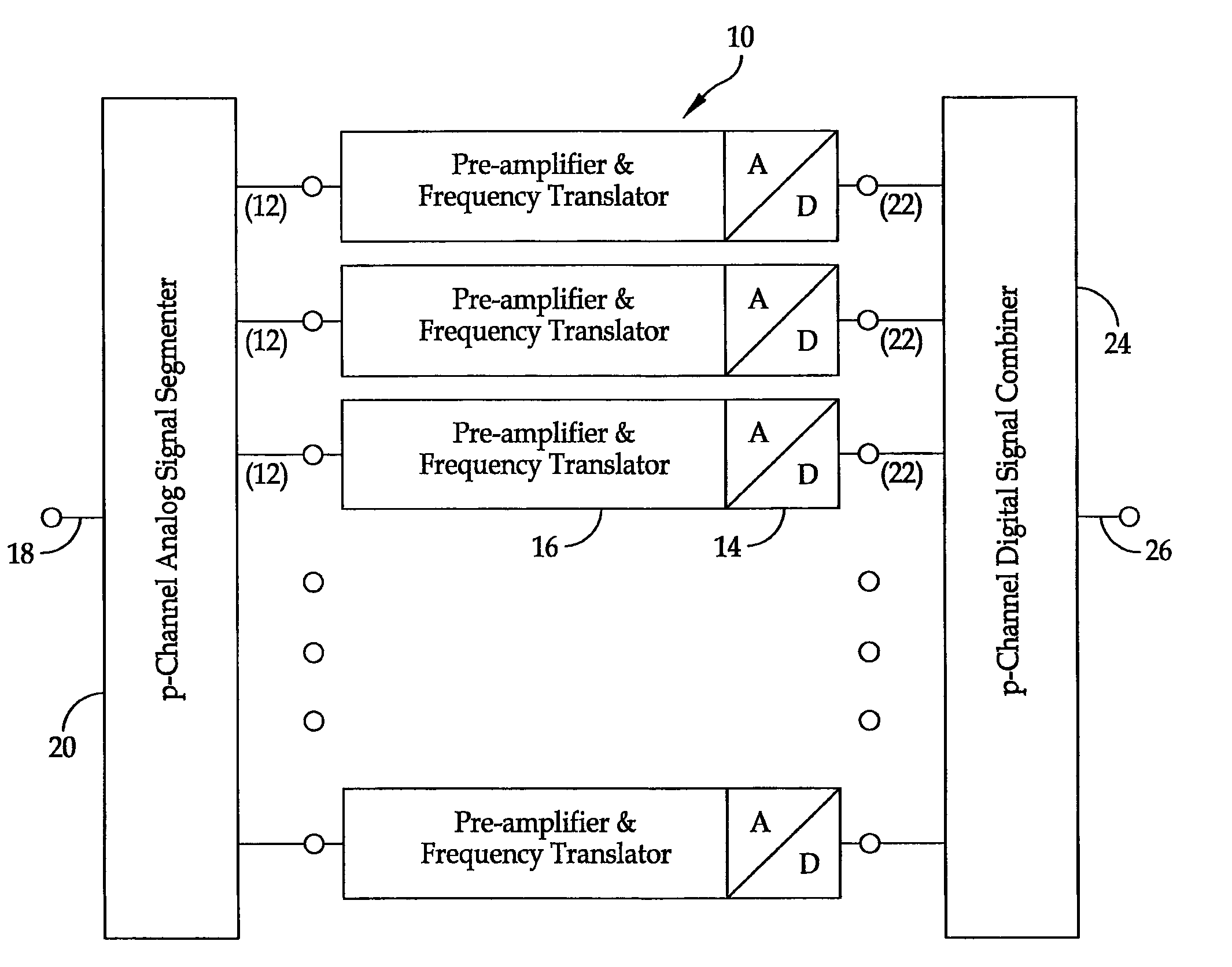
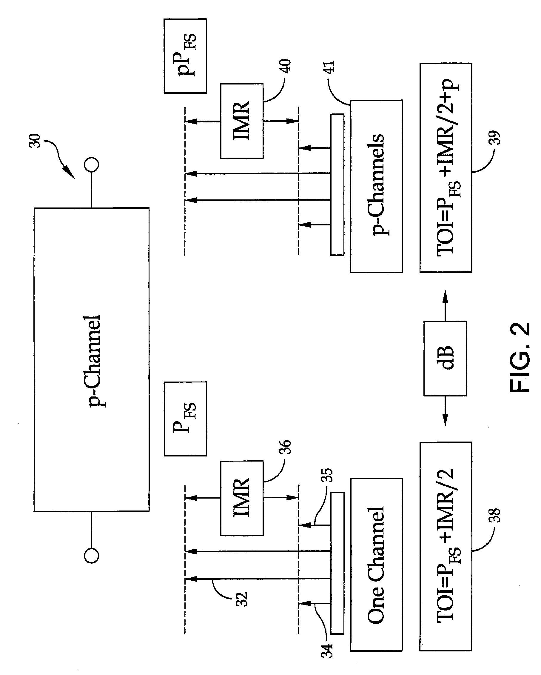
A method is provided for the design of a wide-band high dynamic-range electromagnetic signal receiving system. The method provides for receiving a plurality of analog signals, converting the plurality to a digital replica that can be processed to recover separate high-fidelity replicas of each individual signal in the received plurality. The method also provides increasing the signal dynamic range with a parallel architecture comprising “p” identical parallel analog-to-digital channels wherein the value of is determined by the ratio of the largest amplitude signal to the minimum detectable signal. Further, it is demonstrated that “p” is the fundamental limit on the number of parallel channels necessary to linearly process a specified plurality of signals containing a largest signal and a minimum detectable signal.

Description

[0001]This application claims the benefit of U.S. Provisional Patent Application No. 61 / 277,938 filed on Sep. 30, 2009 and entitled “A Broadband High Dynamic Range Digital Receiving System for Electromagnetic Signals” by the inventor, Donald H. Steinbrecher.STATEMENT OF GOVERNMENT INTEREST[0002]The invention described herein may be manufactured and used by or for the Government of the United States of America for governmental purposes without the payment of any royalties thereon or therefore.CROSS REFERENCE TO OTHER PATENT APPLICATIONS[0003]None.BACKGROUND OF THE INVENTION[0004](1) Field of the Invention[0005]The present invention relates to a digital receiving system for electromagnetic signals.[0006](2) Description of the Prior Art[0007]In the field of signal acquisition systems, there is a need for jam-resistant wideband multifunction digital systems.To address this need, U.S. Pat. Nos. 6,466,167 and 7,250,920 disclose segmenting an air interface as part of a communications syste...

Claims


Application Information

Patent Timeline
IPC IPC(8): H04B7/10
CPCH04B17/00H04B17/345H04B17/327
Inventor STEINBRECHER, DONALD H.
Owner THE UNITED STATES OF AMERICA AS REPRESENTED BY THE SECRETARY OF THE NAVY
Learn More