
Fuel injection device

a fuel injection device and fuel injection technology, applied in the direction of contact members penetrating/cutting insulation/cable strands, machines/engines, transportation and packaging, etc., can solve the problem of difficult to distinguish the error insertion of lead wires, and achieve the effect of easy identification and easy identification

Active Publication Date: 2013-03-19
DENSO CORP
View PDF8 Cites 1 Cited by
  • Summary
  • Abstract
  • Description
  • Claims
  • Application Information

AI Technical Summary

Benefits of technology

The present invention relates to a fuel injection device with improved accuracy and ease of detection of errors in the lead wires at the contact points between guide members. The device includes a nozzle for injecting fuel, a pressure control portion, and a body with a lead wire hole through which two lead wires connected to the pressure control portion are introduced. The lead wire hole has a bent portion and two guide members with guide grooves are inserted into the lead wire hole to ensure proper guidance of the wires. A partition member is provided to partition the guide grooves from each other. The guide members have protrusion and recess portions that fit together to prevent incorrect insertion of the wires and facilitate easy detection of errors. The guide members can also have distinguishing portions to distinguish their arrangement direction. The invention improves accuracy and ease of detection of errors in the fuel injection device.

Problems solved by technology

In addition, even if an error insertion of the lead wires is caused, it is difficult to distinguish the error insertion of the lead wires.

Method used


Image

  • Fuel injection device
  • Fuel injection device
  • Fuel injection device

Examples


Embodiment Construction

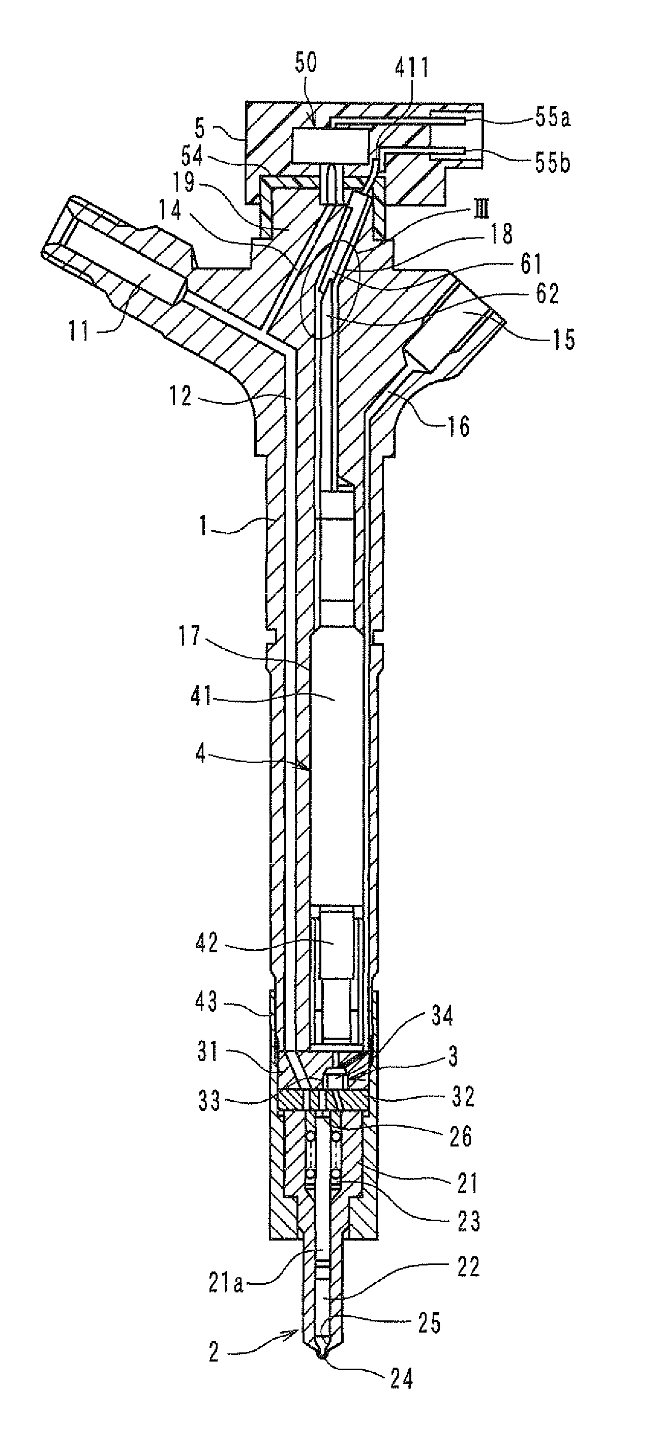
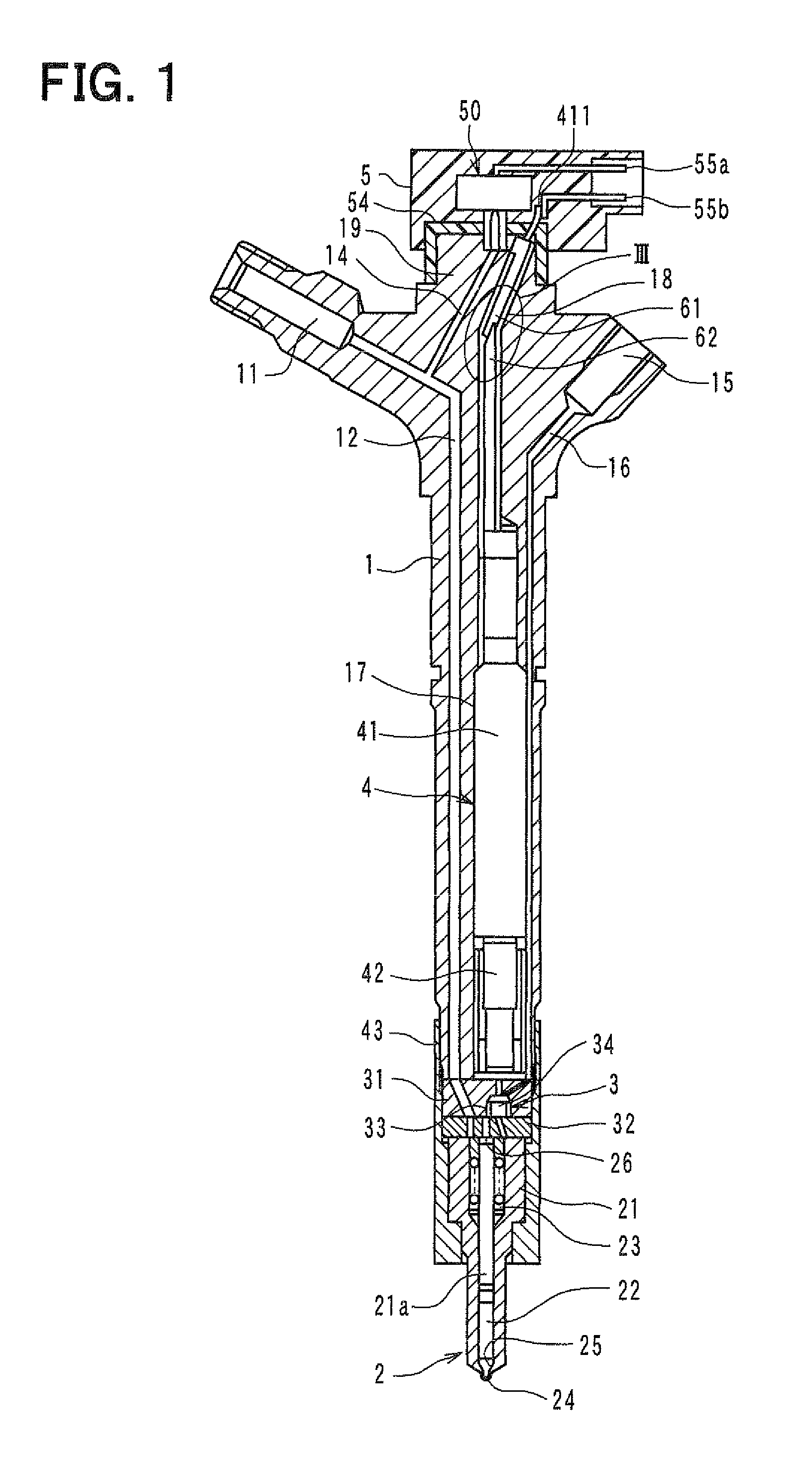
[0022]An embodiment of the present invention will de described with reference to FIGS. 1 to 5B. FIG. 1 shows an entire structure of a fuel injection device according to the embodiment. The fuel injection device is attached to a header of a cylinder in an internal combustion engine (e.g., diesel engine), so as to inject high-pressure fuel accommodated in a common rail to the cylinder of the internal combustion engine.

[0023]The fuel injection device includes a body portion 1 which is formed by forging or cutting a metal member of an iron alloy, for example. The body portion 1 of the fuel injection device is provided with a fuel inlet portion 11, a high-pressure fuel passage 12, a high-pressure fuel branch passage 14, a fuel outlet portion 15, a low-pressure fuel passage 16, a cylindrical receiving hole 17, and a cylindrical lead wire hole 18. High-pressure fuel from the common rail is introduced into the fuel inlet portion 11, and the high-pressure fuel introduced into the fuel inlet ...


PUM


Abstract

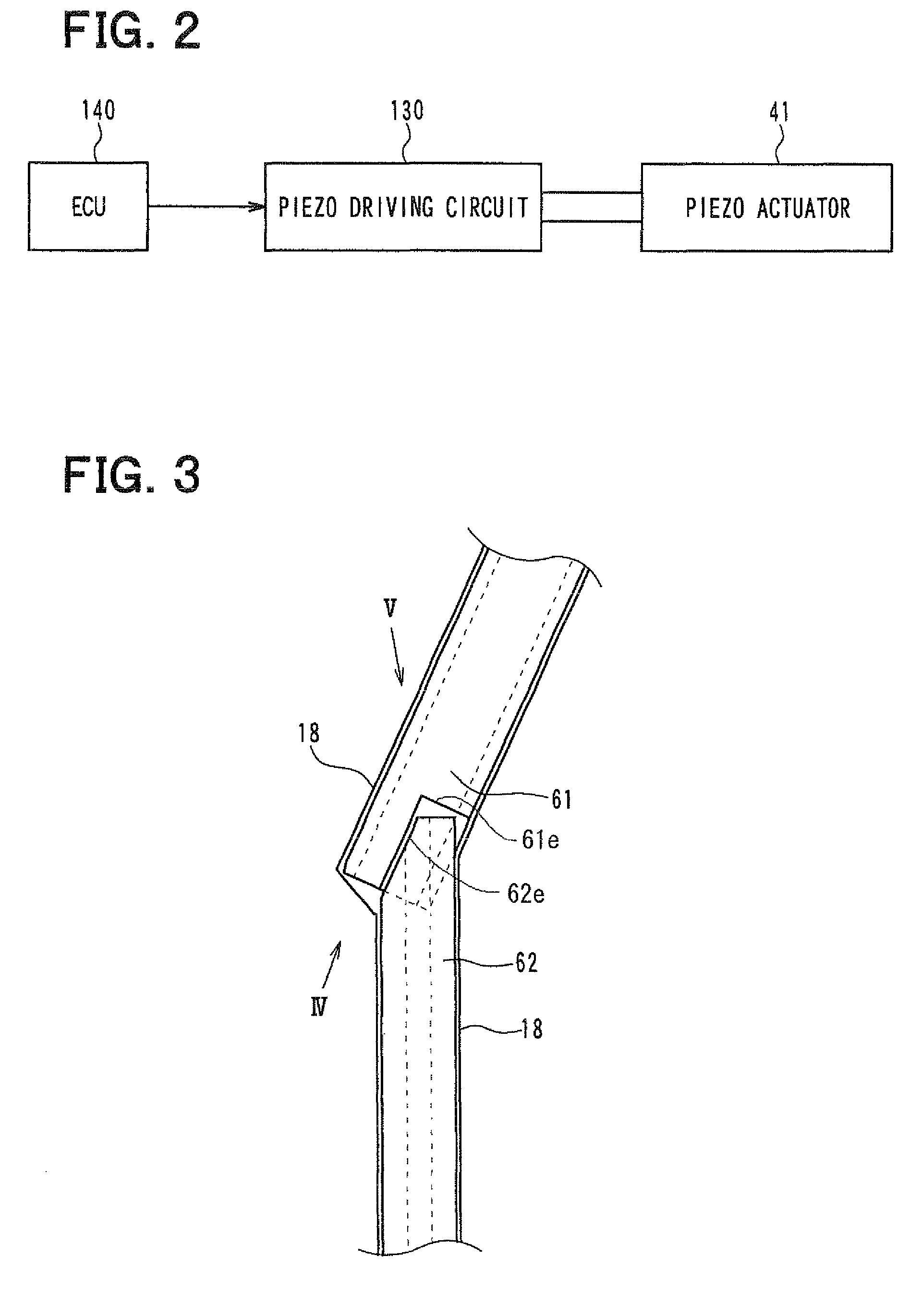
A fuel injection device includes a pressure control portion for controlling operation of a nozzle, and a body portion having therein a bent lead wire hole through which two lead wires of the pressure control portion are introduced to exterior. A first guide member having therein a pair of first guide grooves partitioned by a first partition member is inserted into the lead wire hole from one end side, a second guide member having therein a pair of second guide grooves partitioned by a second partition member is inserted into the lead wire hole from the other end side. The first partition member protrudes from one end portion of the first guide member to have a protrusion portion, which is fitted with a recess portion of the second partition portion at one end portion of the second guide member when the first and second guide members contact.

Description

CROSS REFERENCE TO RELATED APPLICATION[0001]This application is based on Japanese Patent Application No. 2009-090702 filed on Apr. 3, 2009, the contents of which are incorporated herein by reference in its entirety.FIELD OF THE INVENTION[0002]The present invention relates to a fuel injection device for injecting fuel to an internal combustion engine, for example.BACKGROUND OF THE INVENTION[0003]Conventionally, JP 2008-240544A describes regarding a fuel injection device including a pressure control portion for controlling injection of fuel. The pressure control portion controls a pressure applied to a nozzle needle in accordance with an electrical signal input by an engine ECU, thereby controlling a nozzle opening and closing operation.[0004]In the fuel injection device, a lead wire hole is provided in a body portion, so that two lead wires connected to the pressure control portion are introduced to exterior via the lead wire hole. A guide member having therein a pair of guide groove...

Claims


Application Information

Patent Timeline
Patent Type & Authority Patents(United States)
IPC IPC(8): F02M47/02H01R9/05H01R4/24H01R4/00B05B1/30H02G3/18F02M51/00H02G3/06H02G15/08H01R4/26H01R11/20H01R9/22
CPCF02M57/005Y10T137/6851
Inventor KAGAMI, SHUKONDO, JUNFUJINO, TOMOKI
Owner DENSO CORP
Learn More