
Bore-hole jet device for formation hydraulic fracturing and horizontal well examination and a method for the operation thereof

a jet device and hydraulic fracturing technology, applied in the field of pump engineering, can solve the problems of narrowing the application range of the claimed method and the proposed bore-hole jet device for implementing, and not fully enabling the use of the possibility of the jet device, so as to improve the reliability of the jet devi

Inactive Publication Date: 2013-03-19
KHOMYNETS ZINOVIY DMITRIEVICH
View PDF8 Cites 6 Cited by
  • Summary
  • Abstract
  • Description
  • Claims
  • Application Information

AI Technical Summary

Benefits of technology

The invention aims to improve the reliability and productivity of the bore-hole jet device when testing a well. It does this by increasing its functionality during surveying and testing wells, which involves optimizing operational sequence and ensuring the most efficient use of equipment installed on a pipe string. The invention provides a set of elements that enable a sequence of actions during executing the method for operating the bore-hole jet device, which ensures the most efficient use of the equipment installed on a pipe string during carrying out works on surveying, testing, and development of producing formations in horizontal wells. It also allows for monitoring of a pressure drawdown value by controlling the pumping rate of an active working medium, adjusting the mode of pumping out by changing a pressure of an active nozzle, and preliminary installation of any functional inserts into the jet pump without the need for additional tools. The invention saves time for their removal and also avoids the possibility of plugging the mixing chamber and nozzle with mechanical impurities from hydrofracturing liquid. The result is intensive works on surveying, testing, and developing wells, which improves the reliability of the bore-hole jet device.

Problems solved by technology

However, the possibilities of this bore-hole jet device are not used in full because a big timetable is required for replacement of inserts, which is often greater than an estimated time of reactions between an acid solution and minerals of a producing formation.
However, this device does not enable using its possibilities in full, since it allows to carry out surveys of producing rocks only in well bores that are nearly vertical, thus narrowing the applications of the claimed method and the bore-hole jet device proposed for implementing it.
Moreover, a rather labor-consuming operation on releasing the packer and subsequently installing it in a new place is, as a rule, required for rearranging the jet pump, which increases the time necessary for carrying out full-scale surveys.

Method used


Image

  • Bore-hole jet device for formation hydraulic fracturing and horizontal well examination and a method for the operation thereof
  • Bore-hole jet device for formation hydraulic fracturing and horizontal well examination and a method for the operation thereof
  • Bore-hole jet device for formation hydraulic fracturing and horizontal well examination and a method for the operation thereof

Examples


Embodiment Construction

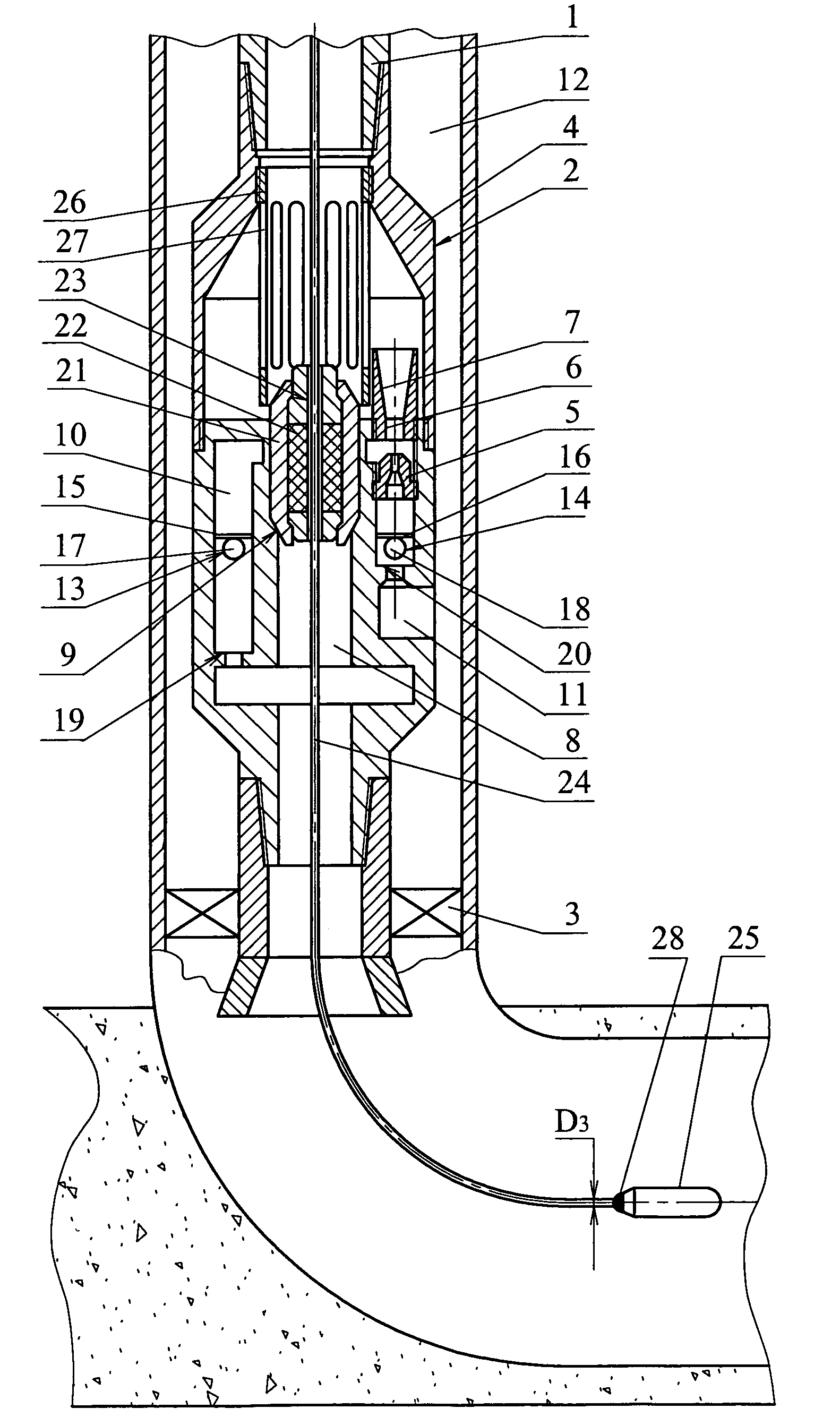
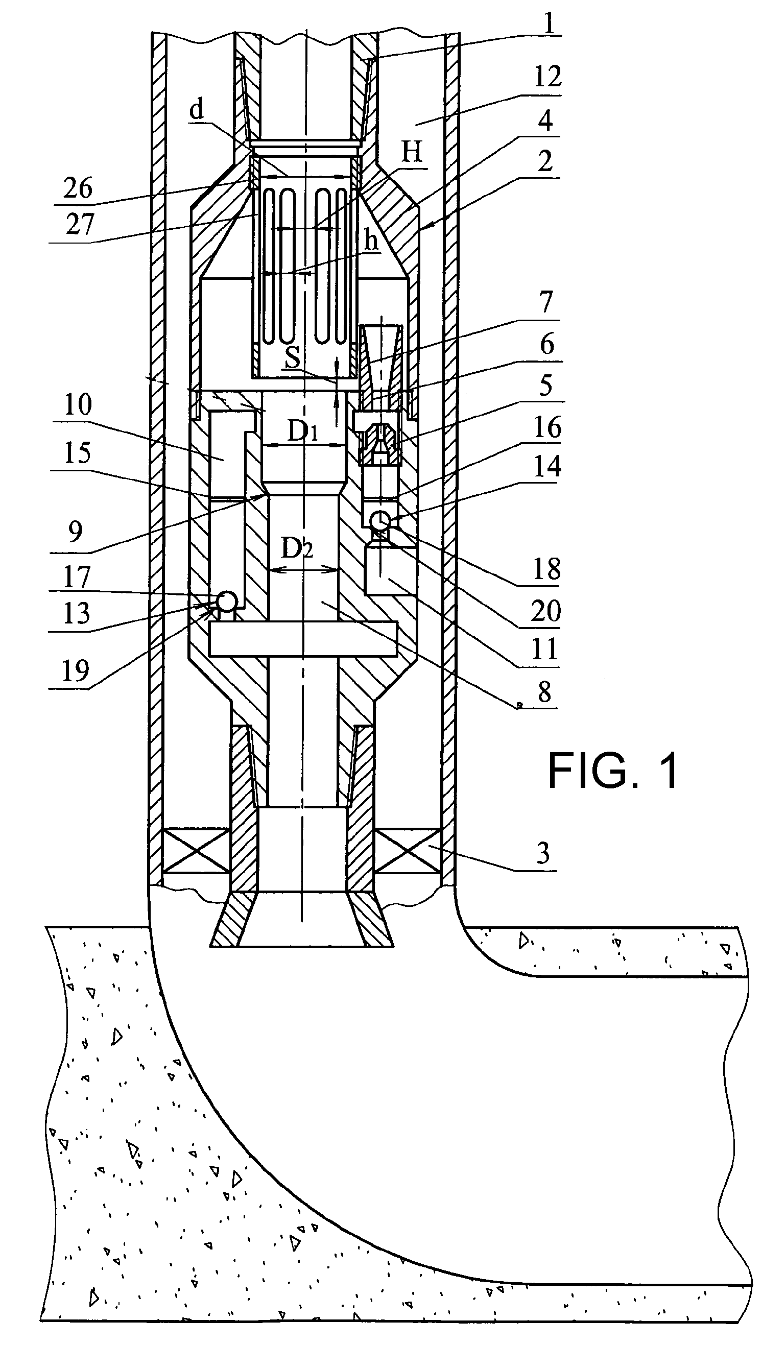
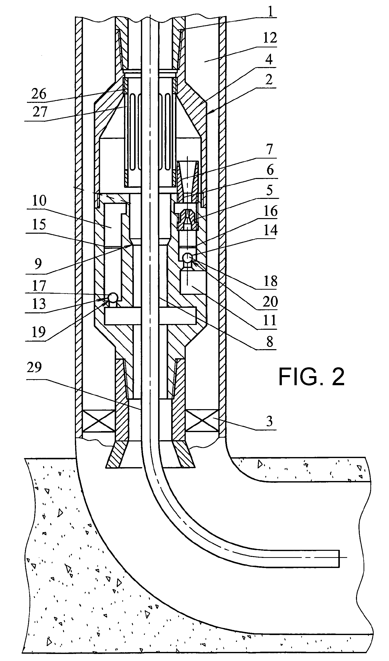
[0025]The bore-hole jet device comprises a jet pump 2 and a packer 3, which are installed on a pipe string 1. The body 4 of the jet pump 2 is provided with an active nozzle 5 and a mixing chamber 6 with a diffuser 7, which are arranged coaxially, as well as with a stepped pass channel 8 narrowing from top downwards and having a seat 9 between its steps, a channel 10 for supplying a fluid pumped out of a well, communicating with the stepped pass channel 8 below the seat 9, and a channel 11 for supplying an active working medium, communicating on its outlet with the active nozzle 5 and on its inlet with the hole annulus 12 around the pipe string 1. The stepped pass channel 8 is made coaxially to the pipe string 1 and communicates with it. The channel 10 for supplying a fluid pumped out of a well and the channel 11 for supplying an active working medium are each provided with a check valve 13, 14, respectively, and with a limit stop 15, 16 for upward movement of a shutoff member 17, 18...


PUM


Abstract

A jet pump body comprises nozzle and mixing chamber with diffuser, coaxially arranged, and a stepped through channel, tapers downward and provided with a seat between steps. The channel is made coaxially with a pipe string. Channels provided with return valve and restrictor for limiting locking member displacement of the return valve upward respective to the seat. A hollow stepped sealing unit with sealing element can be arranged in the through channel. An axial channel is made in the sealing element. A guiding separation bushing cantilever fitted by the top end thereof to the top part of the body of the pump mounts above the channel axially thereto in the pump body. Longitudinal slotted orifices are made in the separation bushing wall.

Description

FIELD OF THE INVENTION[0001]The invention relates to the field of pump engineering, primarily to bore-hole jet devices for formation hydrofracturing, well testing and surveying.BACKGROUND ART[0002]A bore-hole jet device is known that comprises a packer provided with a central channel and a jet pump which body is provided with an active nozzle and a mixing chamber with a diffuser as well as a channel for supplying a working medium and a channel for supplying a fluid pumped out of a well, the packer and the pump being arranged on a pipe string, the jet pump body being also provided with a pass channel with the possibility of installing replaceable functional inserts and a sealing unit therein (see, RU Patent No. 2176336 C 1, F04F 5 / 02, Nov. 27, 2001).[0003]The same patent teaches a method for operating a bore-hole jet device, including arranging the jet pump on a flow string in a well, pumping a chemical agent via the flow string into a formation and subsequently pumping reaction prod...

Claims


Application Information

Patent Timeline
Patent Type & Authority Patents(United States)
IPC IPC(8): E21B47/06E21B47/00F04F5/54
CPCE21B43/124F04F5/464E21B47/00E21B43/26
Inventor KHOMYNETS, ZINOVIY DMITRIEVICH
Owner KHOMYNETS ZINOVIY DMITRIEVICH
Learn More