
Beverage dispenser with capacitive level sensor and display and method

a capacitive level sensor and beverage dispenser technology, applied in the field of insulated beverage dispensers, can solve the problems of false reading, capacitance of capacitors, and inability to determine how much beverage remains in the beverage dispenser, and achieve the effect of reducing power consumption

Active Publication Date: 2013-03-05
FOOD EQUIP TECH
View PDF2 Cites 26 Cited by
  • Summary
  • Abstract
  • Description
  • Claims
  • Application Information

AI Technical Summary

Benefits of technology

The patent describes a technology that reduces power consumption in electronic devices by using a wake-up feature to only briefly query inputs and outputs. This feature, along with a low power consumption state for the controller, results in a significant improvement in battery life for devices that use this technology.

Problems solved by technology

A problem with such insulated dispensers is that they are opaque, often made from stainless steel or the like, and consequently it is not possible to determine how much beverage remains in the dispenser after service has begun without opening the top.
A problem with this known capacitive-type level sensor is that the capacitances of the capacitors change with changes in temperature of the beverage to give a false reading.
A problem with the resistive-type levels sensor is that the resistive, conductive element must be in direct contact with the beverage which can lead to corrosion and circuit failure.
Also, in known sensing circuits have not been able to take advantage of existing off-the-shelf integrated circuitry.
A problem with known capacitive sensing circuits is that their power consumption results in relatively rapid depletion of the battery.
This is due in part to the use of relatively large capacitors that have been believed needed for accurate sensing and a failure to take advantage of the low power consumption, accuracy and reliability off-the-shelf micro-integrated circuitry.

Method used


Image

  • Beverage dispenser with capacitive level sensor and display and method
  • Beverage dispenser with capacitive level sensor and display and method
  • Beverage dispenser with capacitive level sensor and display and method

Examples


Embodiment Construction

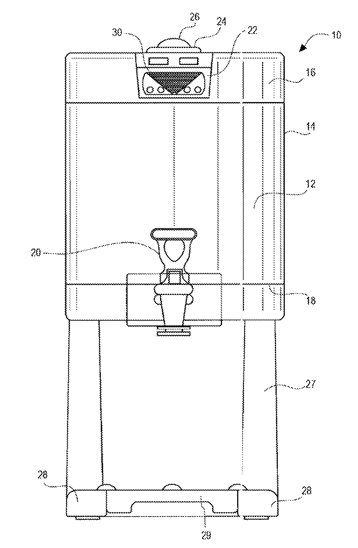
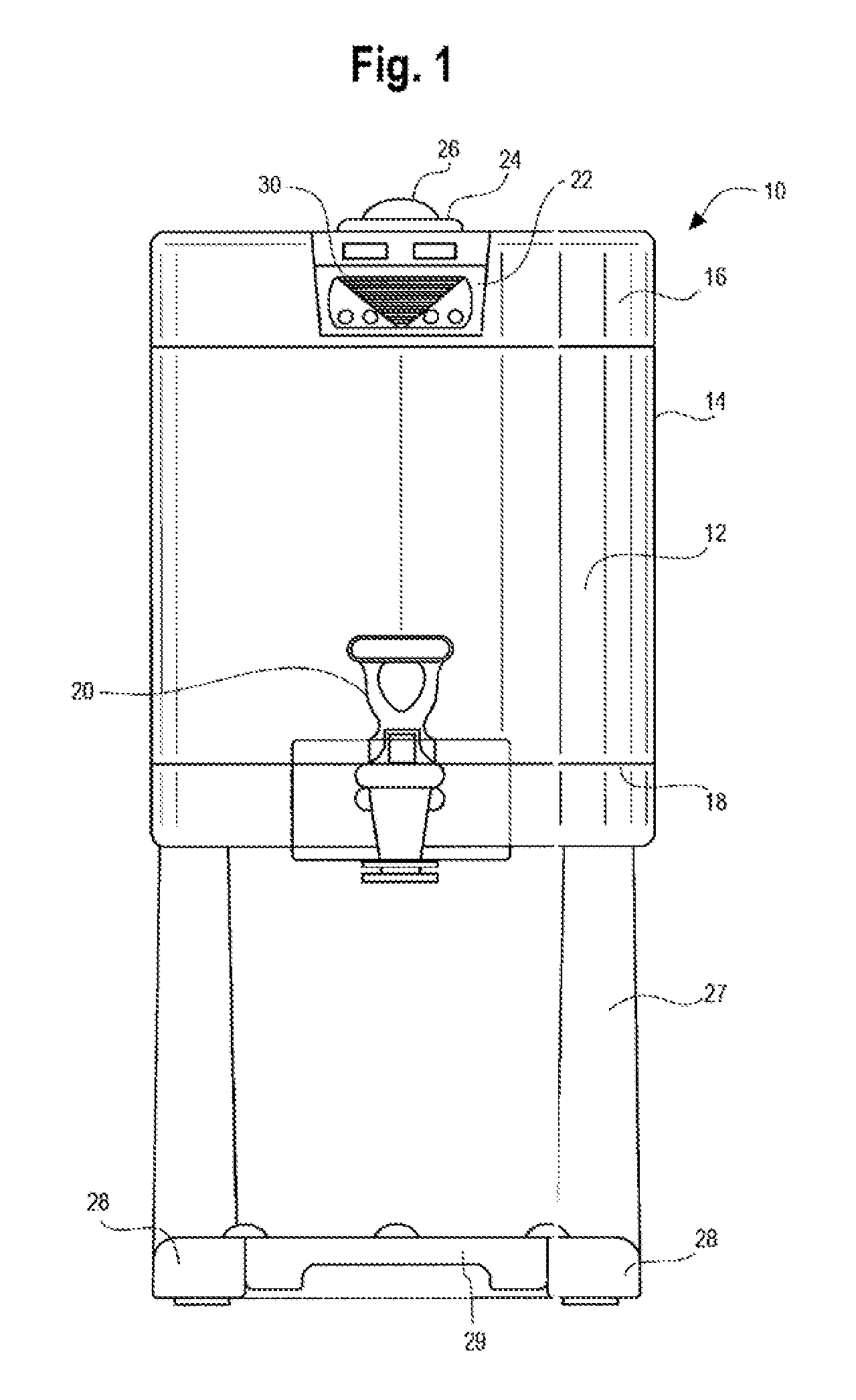
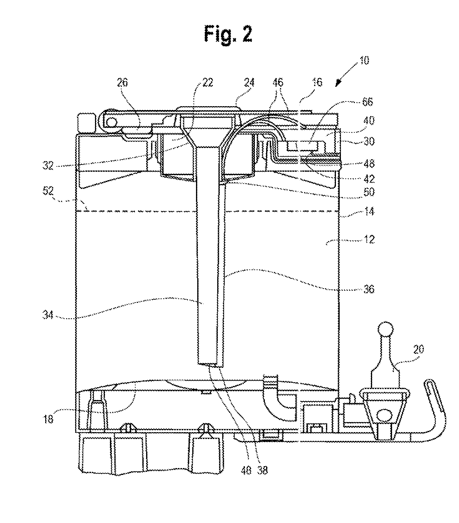
[0031]Referring to FIG. 1, a preferred embodiment of the quantity indicating beverage dispenser assembly 10 is seen to have an insulated, dispenser body 12 with a cylindrical sidewall 14 extending between a cylindrical top closure 16 and a bottom 18. A manually actuatable faucet 20 is mounted to the sidewall 14 adjacent the bottom 18 to selectively drain beverage from the dispenser body 12. Releasably mounted within a mounting hole in the top closure 16 is a funnel assembly 22 with a funnel inlet 24, selectively closed by a plug 26. When beverage is being received into the funnel inlet, the plug 26 is pivoted to a recessed position, as shown in FIG. 2, to enable the dispenser to be located closely beneath the drain hole of the mating beverage brewer (not shown), such as shown in U.S. Pat. No. 6,741,180, referenced above, and reference should be made thereto with respect to these details. The bottom 18 of the body 13 is supported by a U-shaped leg assembly 27 with two forwardly exten...


PUM


Abstract

A beverage dispenser (10) with a beverage quantity indicating display (30) controlled by a microprocessor (66) in response to variations in capacitance of a plurality of sensing capacitors (72) detected by a capacitive sensing circuit (70) including one of a general purpose input / output integrated capacitive touch-key sensor, and a general purpose, integrated, input / output port expander with an integrated capacitive touch-key for reduced power consumption, sensitivity and reliability. A reference capacitor (C8) is located above the maximum height (52) of the beverage (74) to keep it spaced from the beverage (74) in air is used to compensate for changes in capacitance of the sensing capacitors (72) due to variations in temperature. All the capacitors (72, C8) are formed from pairs of planer conductive plates (54, 56) respectively mounted to opposed parallel interior surfaces (58, 60) of a sensing tube (36) attached to a down tube (34).

Description

CROSS REFERENCE TO RELATED APPLICATION[0001]This application claims the benefit under 35 U.S.C. 119(e) of provisional patent application No. 61 / 163,603, filed Mar. 26, 2009, and bearing the same title as the present application, and claims the benefit under 35 U.S.C. 120 of pending application Ser. No. 12 / 250,963 filed Oct. 14, 2008, and entitled “Beverage Dispenser with Level Measuring Apparatus and Display” which claims the benefit under 35 U.S.C. 119(e) of provisional application No. 60 / 999,682, filed Oct. 19, 2007, all of which applications together with any associated appendices, exhibits or the like, are hereby incorporated by reference.BACKGROUND OF THE INVENTION[0002]1. Field of the Invention[0003]This invention generally relates to opaque insulated beverage dispensers with faucets for dispensing beverage and, more particularly, to such dispensers with a beverage quantity electronic display and related methods of determining and displaying quantity.[0004]2. Discussion of the...

Claims


Application Information

Patent Timeline
IPC IPC(8): G01F23/26
CPCG01F23/265G01F23/266
Inventor KAMINSKI, ANDRZEJ
Owner FOOD EQUIP TECH
Learn More