
Power amplifier time-delay invariant predistortion methods and apparatus

a technology of time-delay and power amplifier, which is applied in the field of time-delay invariant predistortion methods and apparatuses of power amplifiers, can solve the problems of difficult to measure in a laboratory such a time-delay parameter, significant problems with respect to the accuracy of predistortion correction, and increase the difficulty of testing such intrinsic time-delay parameters. , to achieve the effect of improving power efficiency and spectrum efficiency, simple circuit structure, and convenient implementation

Inactive Publication Date: 2013-02-19
DALI WIRELESS
View PDF95 Cites 40 Cited by
  • Summary
  • Abstract
  • Description
  • Claims
  • Application Information

AI Technical Summary

Benefits of technology

This approach results in improved power and spectrum efficiency, enabling self-calibration and effective non-linear correction in wireless RF transmitter systems, with a simpler circuit structure that can be applied across various wireless communication systems, including base-stations and mobile devices.

Problems solved by technology

This difference, usually referred to as a time delay, presents significant problems with respect to the accuracy of the predistortion correction.
These problems are made worse by the fact that the time delay can vary with environmental conditions including temperature, system conditions including signal power level, system aging, and so on.
Therefore, it is difficult to measure in a laboratory such an intrinsic time-delay parameter, and, moreover, a parameter for correcting the time-delay cannot be designed as a constant.
This approach suffers the limitation that the time-delay cable imposes a fixed time-delay that cannot be adjusted despite changes in the signal and environment which naturally occur during the operation of practical systems.
However, an extra circuit, typically a latch, and an associated algorithm are needed, and the accuracy of the time-delay calculation is also related to the convergence rate of the algorithm.

Method used


Image

  • Power amplifier time-delay invariant predistortion methods and apparatus
  • Power amplifier time-delay invariant predistortion methods and apparatus
  • Power amplifier time-delay invariant predistortion methods and apparatus

Examples


Embodiment Construction

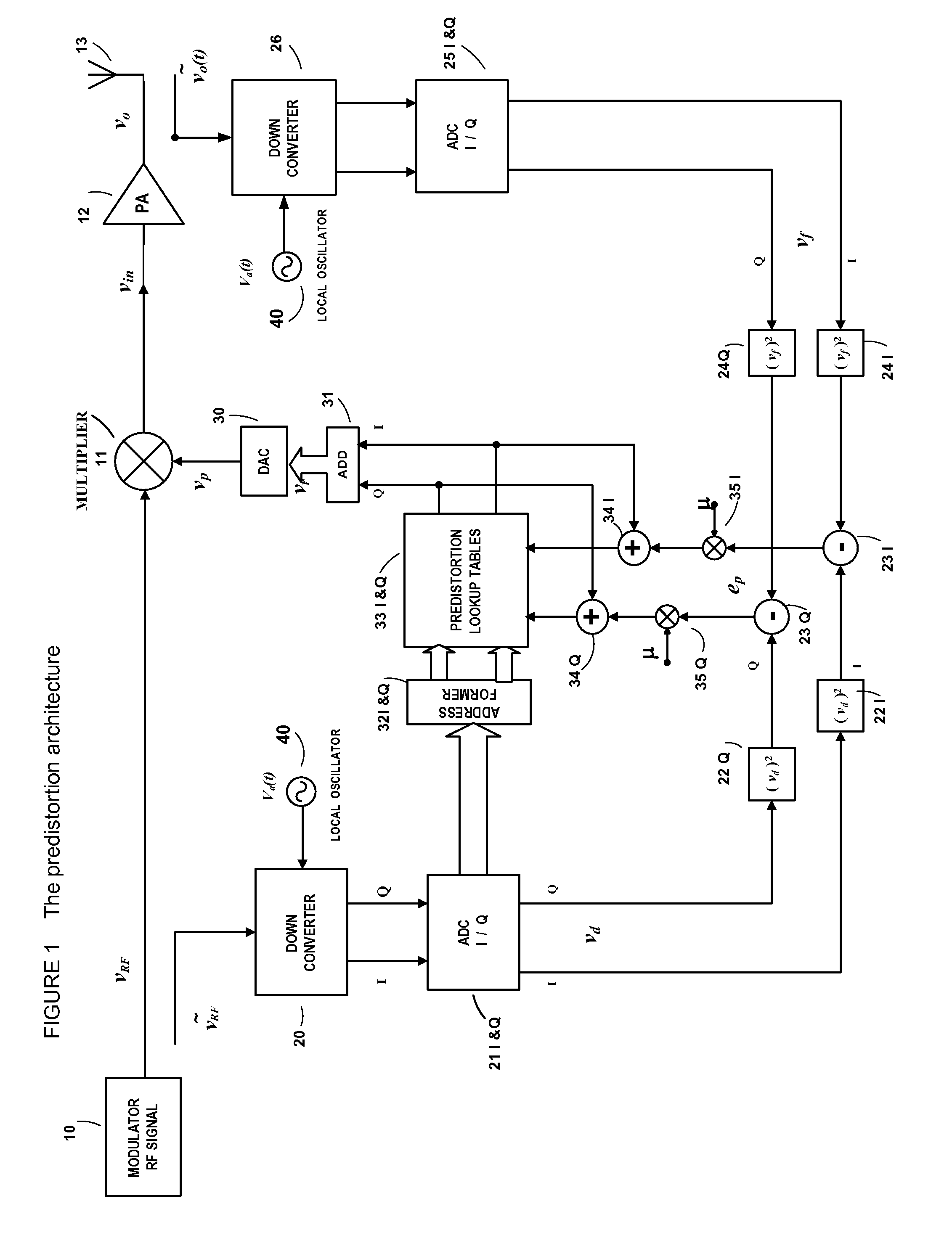
[0014]In one implementation of the invention, the entries for the lookup table are developed in accordance with the techniques described in pending U.S. patent application Ser. No. 11 / 262,079, filed Oct. 27, 2005, and U.S. patent application Ser. No. 11 / 799,239, filed Apr. 30, 2007, both of which are incorporated herein by reference. It will be appreciated by those skilled in the art that the range of errors which occur in a real-world system are bounded; that is, there is a range which has a minimum value and a maximum value, and in all but rare circumstances the correction factor applicable at the time of any given sample will fall within that range. By selecting a lookup table of appropriate size, and populating the lookup table with appropriate values as determined by the methods in the above-mentioned patent, which are selected over the entire operating spectrum of the PA and associated system, the correction factor which is appropriate for each sampling of the input signal wil...


PUM


Abstract

An embodiment of the invention is a time-delay invariant predistortion approach to linearize power amplifiers in wireless RF transmitters. The predistortion architecture is based on the stored-compensation or memory-compensation principle by using a combined time-delay addressing method, and therefore, the architecture has an intrinsic, self-calibrating time-delay compensation function. The predistortion architecture only uses a lookup table to conduct both the correction of non-linear responses of a power amplifier and the compensation of any time-delay effects presented in the same system. Due to the time-delay invariant characteristic, the predistortion design has a wider dynamic range processing advantage for wireless RF signals, and therefore can be implemented in multi-carrier and multi-channel wireless systems.

Description

RELATED APPLICATIONS[0001]This application is a continuation-in-part of U.S. patent application Ser. No. 11 / 262,079, filed Oct. 27, 2005, titled “System and Method for Digital Memorized Predistortion for Wireless Communication,” which in turn is a continuation of U.S. patent application Ser. No. 10 / 137,556, filed May 1, 2002, now U.S. Pat. No. 6,985,704, issued Jan. 10, 2006 titled “System and Method for Digital Memorized Predistortion for Wireless Communication,” both of which are incorporated herein by reference. This application claims the benefit of the foregoing applications and also claims the benefit of S. Provisional Patent Application Ser. No. 60 / 897,746, filed Jan. 26, 2007, titled “Power Amplifier Time-Delay Invariant Predistortion Methods and Apparatus”; U.S. Provisional Patent Application Ser. No. 60 / 898,312, filed Jan. 29, 2007, entitled titled “Power Amplifier Time-Delay Invariant Predistortion Methods and Apparatus,” all of which are incorporated herein by reference....

Claims


Application Information

Patent Timeline
Patent Type & Authority Patents(United States)
IPC IPC(8): H04B1/04
CPCH03F1/3247H03F3/24H03F1/3241H03F2200/451H03F2201/3224H03F2201/3233H03F2200/57H04B1/0475H04B2001/0425H04L1/0044
Inventor YANG, DALIYANG, JIA
Owner DALI WIRELESS
Learn More