
Antenna and wireless communication apparatus

a wireless communication and antenna technology, applied in the field of antennas, can solve the problems of increasing the physical volume occupied by such an antenna, reducing the antenna efficiency, and affecting the service life of the antenna, so as to reduce the interference, reduce the size of the antenna, and improve the service life.

Active Publication Date: 2013-02-19
MURATA MFG CO LTD
View PDF19 Cites 4 Cited by
  • Summary
  • Abstract
  • Description
  • Claims
  • Application Information

AI Technical Summary

Benefits of technology

[0010]In view of the foregoing, preferred embodiments of the present invention provide an antenna that makes it possible to reduce interference between a plurality of antenna parts, ensure satisfactory antenna characteristics required for mono antennae in a plurality of respective frequency bands, and achieve a smaller antenna size. Preferred embodiments of the present invention also provide a wireless communication apparatus that includes such a novel antenna.

Problems solved by technology

Generally speaking, when antenna parts for different systems having a plurality of feeding lines are located near each other, isolation is a major problem.
However, such an approach has a problem in that physical volume occupied by such an antenna increases.
Alternatively, if the distance between one antenna part and the other is made greater without changing the volume thereof, the physical volume of each antenna part decreases, which results in a decrease in antenna efficiency.

Method used


Image

  • Antenna and wireless communication apparatus
  • Antenna and wireless communication apparatus
  • Antenna and wireless communication apparatus

Examples


first preferred embodiment

[0037]FIG. 3A is a perspective view that schematically illustrates the configuration of an antenna according a first preferred embodiment of the present invention. FIG. 3B is a cross-sectional view that schematically illustrates the configuration of the center portion thereof. FIG. 4 is a partial view that schematically illustrates the configuration of the conductor portion and the electrode portion of the antenna illustrated in FIG. 3A and FIG. 3B. In FIG. 3A, an antenna 101 preferably includes a dielectric base 70 as well as conductors and electrodes. The dielectric base 70 has a predetermined shape. The electrodes and conductors that have a predetermined pattern are formed in / on the dielectric base 70. The dielectric base 70 constitutes a portion of a structural body that is formed inside the frame of a wireless communication apparatus on which the antenna 101 is provided. Therefore, the entire shape of the dielectric base 70 is formed in such a manner that it can be fittingly bu...

second preferred embodiment

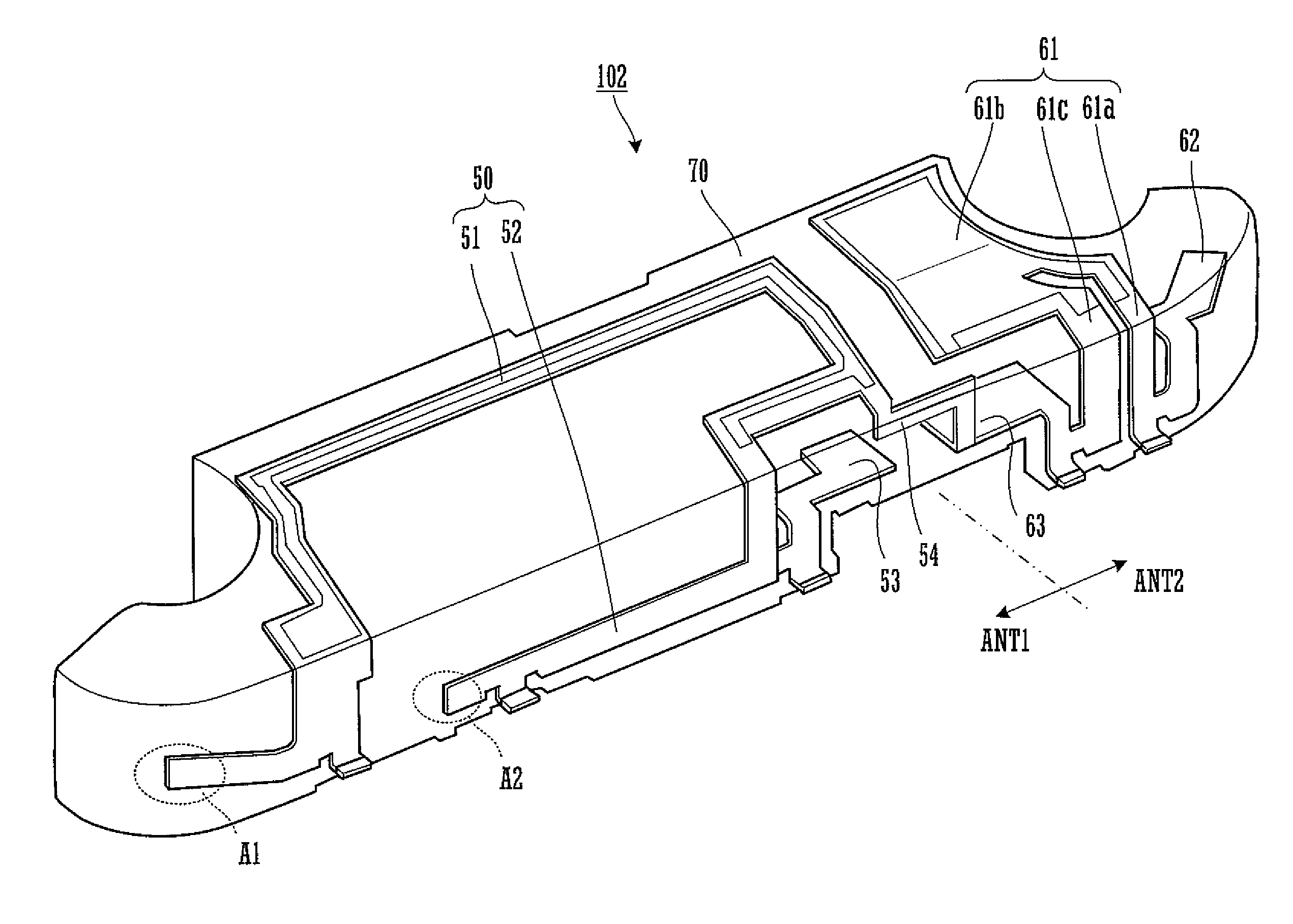
[0052]FIG. 7 is a perspective view that schematically illustrates the configuration of an antenna 102 according to a second preferred embodiment of the prevent invention. The configuration of the antenna 102 according to the second preferred embodiment of the present invention explained below differs from that of the antenna 101 according to the foregoing first preferred embodiment of the present invention, which is illustrated in FIG. 3, in that the first antenna portion ANT1 of the antenna 102 according to the second preferred embodiment of the present invention is provided with a matching ground connection electrode whereas the first antenna portion ANT1 of the antenna 101 according to the foregoing first preferred embodiment of the present invention is not provided with such an electrode. Specifically, as illustrated in FIG. 7, a matching ground connection conductor 54 is provided between a region of the first antenna portion ANT1 and the ground connection terminal 63 of the sec...


PUM


Abstract

In an antenna, a first type radiation electrode and a second type radiation electrode are provided on the surface of a dielectric base, which has a predetermined external shape, or embedded in the dielectric base. The first type radiation electrode is provided with an open terminal at one end thereof and a feeding terminal at the other end thereof so as to constitute a monopole type antenna. The second type radiation electrode is provided with a capacitive-coupling feeding electrode at one end thereof and a ground connection terminal at the other end thereof so as to constitute a capacitive feed antenna. The one end of the first type radiation electrode is located opposite to the feeding electrode of the second type radiation electrode when viewed in the direction of the length of the dielectric base.

Description

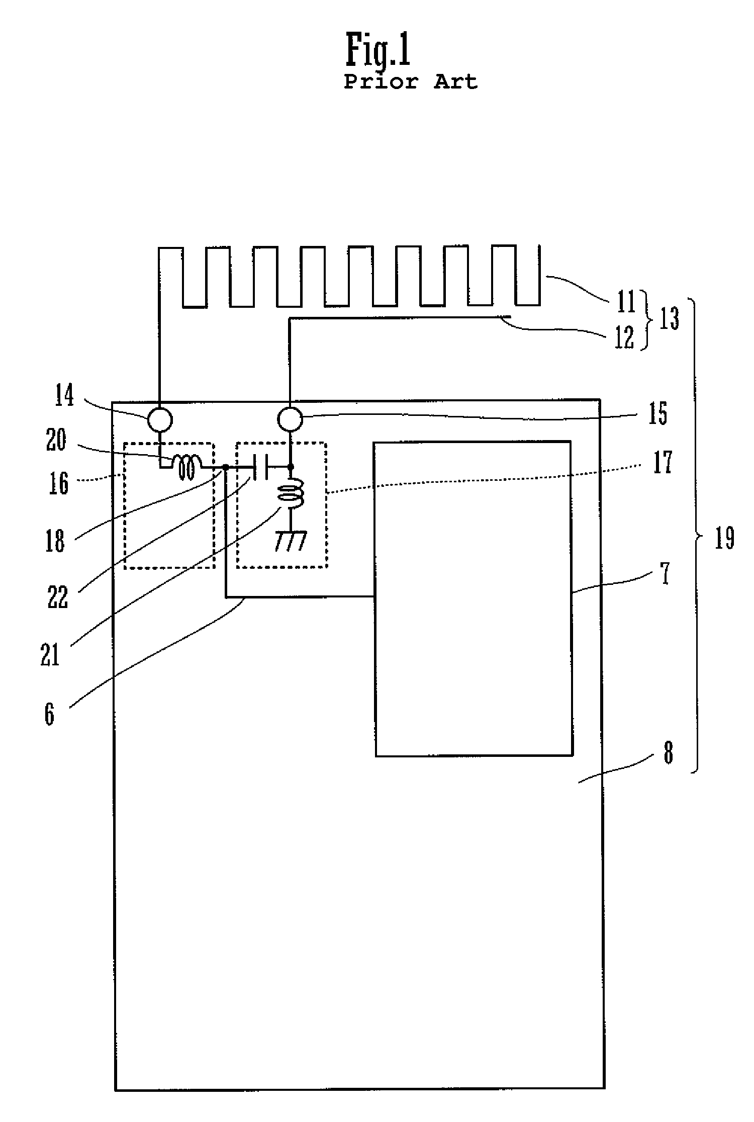
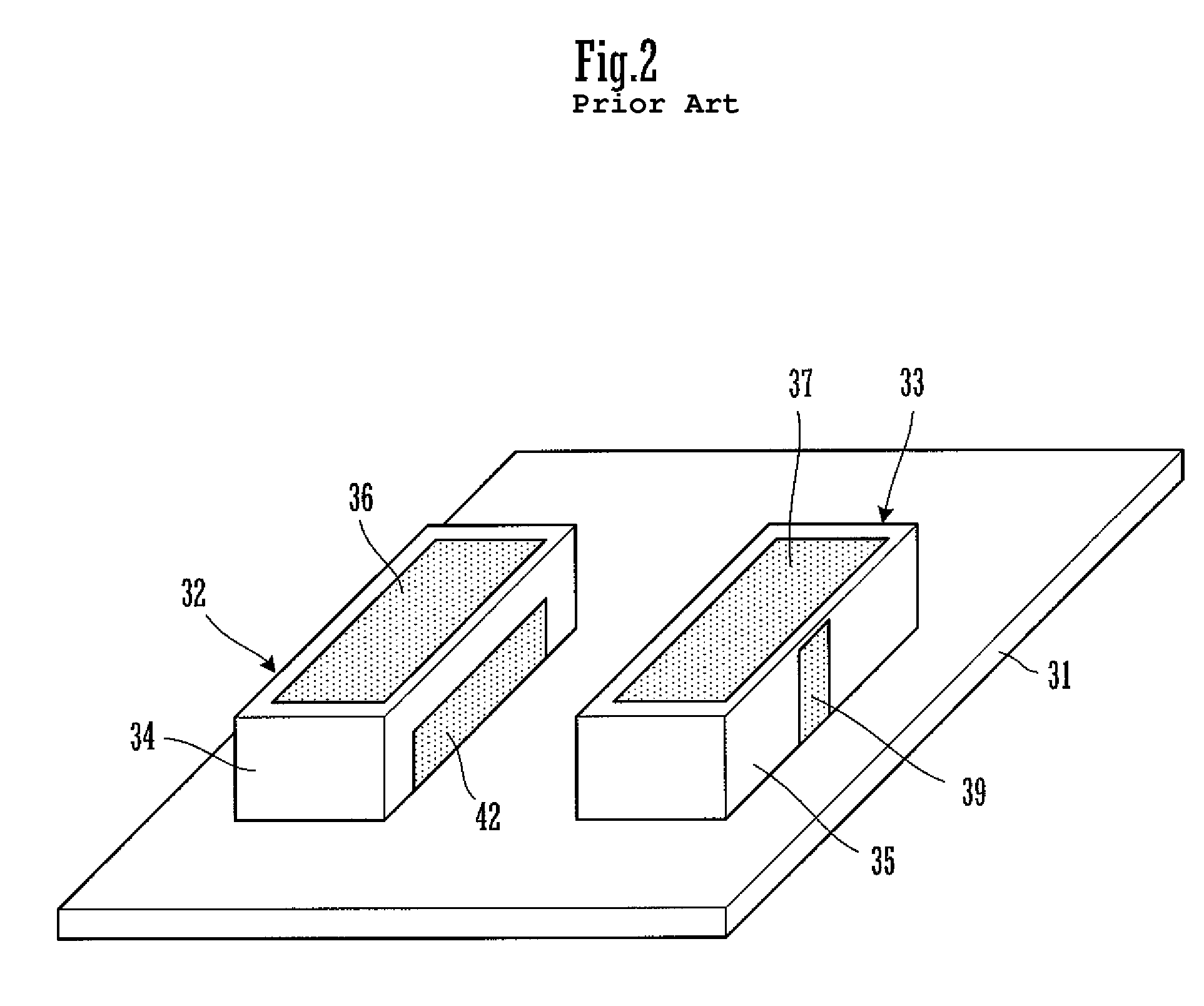
BACKGROUND OF THE INVENTION[0001]1. Field of the Invention[0002]The present invention relates to an antenna for use in, for example, a wireless communication apparatus such as a mobile communication device or other suitable apparatus. In addition, the present invention relates to a wireless communication apparatus that includes such an antenna.[0003]2. Description of the Related Art[0004]An antenna that is used in a plurality of frequency bands in a wireless communication apparatus such as the terminal device (i.e., mobile phone) of a mobile phone system or the like is described in Japanese Unexamined Patent Application Publication No. 2005-244553 and Japanese Unexamined Patent Application Publication No. 2002-252515. FIG. 1 is a diagram that illustrates the configuration of an antenna that is described in the Japanese Unexamined Patent Application Publication No. 2005-244553. As shown in FIG. 1, an antenna 13 includes a first antenna element 11 and a second antenna element 12 arran...

Claims


Application Information

Patent Timeline
Patent Type & Authority Patents(United States)
IPC IPC(8): H01Q1/24H01Q19/00H01Q5/10
CPCH01Q1/243H01Q1/38H01Q9/0421H01Q9/40H01Q9/42H01Q21/28
Inventor SATO, JINKAMINISHI, YUJI
Owner MURATA MFG CO LTD
Learn More