
Amplifier

a low-noise amplifier and amplifier technology, applied in amplifiers, dc-amplifiers with dc-coupled stages, positive-feedback circuit arrangements, etc., can solve the problems of less sensitive receivers, high cost of external matching components, and low insertion loss of amplifying stages in receivers, so as to reduce the cost and die area

Active Publication Date: 2013-02-19
AVAGO TECH INT SALES PTE LTD
View PDF37 Cites 8 Cited by
  • Summary
  • Abstract
  • Description
  • Claims
  • Application Information

AI Technical Summary

Benefits of technology

[0011]In accordance with a first aspect of the present invention, there is provided a configurable low noise amplifier circuit, said low noise amplifier circuit being configurable between one of a first topology in which said low noise amplifier circuit comprises a degeneration inductance whereby said low noise amplifier circuit operates as an inductively degenerated low noise amplifier and a second topology in which said low noise amplifier circuit comprises a feedback resistance whereby said low noise amplifier circuit operates as a resistive feedback low noise amplifier. Hence, the present invention allows provision of either inductively degenerated low noise amplifier functionality or resistive feedback low noise amplifier functionality via a single low noise amplifier circuit. Only a single instance of components common to both of the topologies is required and such component re-use helps to reduce the cost and die area.

Problems solved by technology

However, these external matching components can be expensive, and in some cases it is preferable to use an LNA with internal matching capabilities to appropriately set its input impedance and frequency range matching.
The RF filter preceding the LNA that forms the first amplifying stage in a receiver may have significant insertion loss in some of the radio frequency bands within which the receiver is configured to operate.
The insertion loss can cause the receiver to be less sensitive and have a higher noise figure for these radio frequency bands.
Since the receiver sensitivity in these radio frequency bands is worse, the range between the transmitter and the receiver over which the receiver may be required to operate is reduced, thus making the cellular network design more challenging and more expensive.
In addition, the size of the antenna connected to the receiver may be limited due to space constraints in devices such as mobile stations, thus restricting the performance of the antenna; this is exacerbated at lower frequencies, for example below 1 GHz, where the size of an antenna tends to become larger due to the longer wavelength.
The receiver capability can therefore be degraded leading to decreased link performance.
However, achieving good noise performance without using external matching components prior to the LNA and with adequate current consumption is a challenging task.
Additionally, as well as the expensive and size consuming external components, the cost of the RFIC containing the LNA must also be considered.
From the above it can be seen that there are a number of different design factors to be considered when designing an LNA, and that accommodating some or all of these factors simultaneously can prove difficult.

Method used


Image

  • Amplifier
  • Amplifier
  • Amplifier

Examples


Embodiment Construction

[0046]Several LNA structures are known, each of these having certain benefits and drawbacks regarding their noise performance, overall cost, and input matching capabilities.

[0047]A first known LNA topology is the inductively degenerated LNA topology, a detailed analysis of which has been given in, for example, in D. K. Shaeffer and T. H. Lee, “A 1.5-V, 1.5-GHz CMOS low noise amplifier,” IEEE J. of Solid-State Circuits, vol. 32, no. 5, May 1997, pp. 745-759.

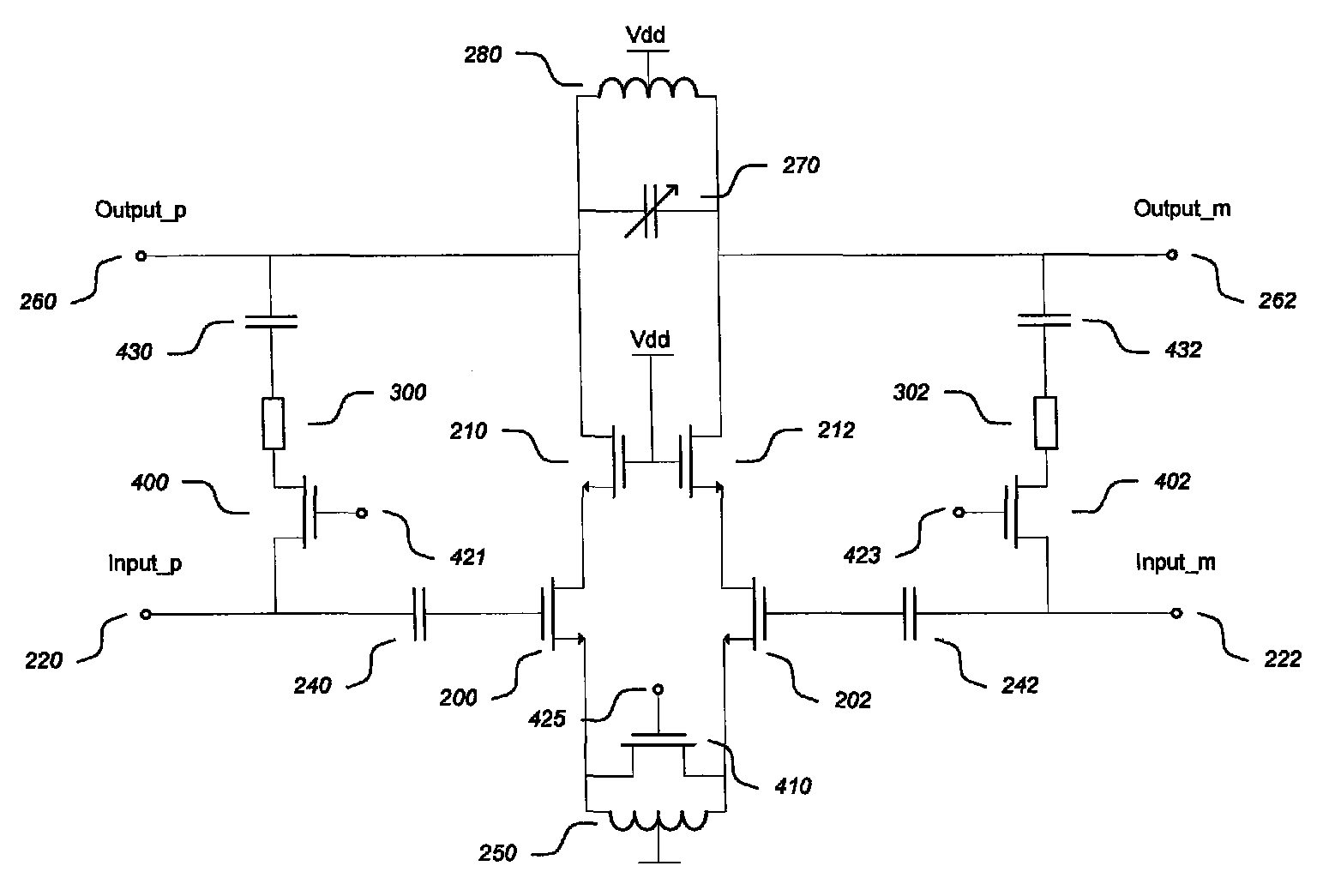
[0048]An exemplary inductively degenerated LNA circuit is depicted in FIG. 2. The LNA of FIG. 2 is a differential amplifier, where transistors 200 and 210 form the positive or ‘plus’ side of the differential amplifier, and transistors 202 and 212 form the negative or ‘minus’ side of the differential amplifier. The plus and minus sides of the differential amplifier are each arranged in a cascode configuration, where transistors 200 and 202, each arranged in a common source configuration, form the input transistors of the plus and m...


PUM


Abstract

The invention relates to a configurable low noise amplifier circuit which is configurable between a first topology in which the low noise amplifier circuit includes a degeneration inductance whereby the low noise amplifier circuit operates as an inductively degenerated low noise amplifier, and a second topology in which the low noise amplifier circuit includes a feedback resistance whereby the low noise amplifier circuit operates as a resistive feedback low noise amplifier.

Description

FIELD OF THE INVENTION[0001]This invention relates to low noise amplifiers. In particular, but not exclusively, this invention relates to configurable low noise amplifier circuits.BACKGROUND OF THE INVENTION[0002]Radio frequency receivers can be configured to operate within a number of different radio frequency bands. For example a receiver for a mobile station (or cellular telephony device) can be configured to operate within any of the following bands: Global System for Mobile Communications (GSM), 850, 900, 1800, and / or 1900, Wideband Code Division Multiple Access (WCDMA), High Speed Packet Access (HSPA) and / or Long Term Evolution (LTE) Bands 1, 2, 3, etc. This allows a mobile station containing such a receiver to be used in different areas where varying subsets of the above radio frequency bands are supported (e.g. to enable roaming).[0003]Receivers typically incorporate one or more Radio-Frequency Integrated Circuits (RFICs) including a Low Noise Amplifier (LNA) as the first am...

Claims


Application Information

Patent Timeline
Patent Type & Authority Patents(United States)
IPC IPC(8): H03F3/45
CPCH03F1/0277H03F1/223H03F1/26H03F1/301H03F1/565H03F3/195H03F3/45179H03F3/45188H03F3/45645H03F3/72H03F2200/135H03F2200/144H03F2200/156H03F2200/159H03F2200/165H03F2200/294H03F2200/39H03F2203/45306H03F2203/45318H03F2203/45386
Inventor HEIKKINEN, JARI JOHANNESRIEKKI, JONNE JUHANIKAUKOVUORI, JOUNI KRISTIAN
Owner AVAGO TECH INT SALES PTE LTD
Learn More