Electric junction box

a junction box and junction box technology, applied in the field of electric junction boxes, can solve the problems of difficult insertion work, difficult to ensure a work space, and difficult to apply the structure to a relay having many terminals, and achieve the effect of large work space for mounting other connection terminals

Inactive Publication Date: 2013-02-19
SUMITOMO WIRING SYST LTD
View PDF32 Cites 0 Cited by
  • Summary
  • Abstract
  • Description
  • Claims
  • Application Information

AI Technical Summary

Benefits of technology

[0010]In view of the above, the present invention provides an electric junction box having a new structure having a vertical bus bar that constitutes a specific connection terminal in a relay mount portion and capable of ensuring a large work space for mounting other connection terminals.
[0012]According to the present invention, the vertical bus bar is provided to the side, not a middle portion, of the relay mount portion. A wide work space can thus be ensured on the second opening side of the terminal connection holes of the relay mount portion. In addition, the flat bus bar portion is extended from the vertical bus bar provided to the side. Power supply to the relay terminals from the vertical bus bar can thus be achieved without the bus bar significantly projecting from the second opening side of the terminal connection holes. As a result, a spacious work space can be ensured, and connection terminals of external wires can easily be inserted to the terminal connection holes with no projection of the bus bar proximate to the work space.
[0015]Further, in addition to the connection terminal for the switch, a connection terminal for a coil side may also be provided to the flat bus bar portion in the present aspect. Thereby, the number of connection terminals and electric wires connected thereto can be reduced without using the bus bar, and thus the terminal connection work can further be simplified.
[0017]With the structure above, the connection terminals for the coil can also be included in the flat bus bar portion, in addition to the connection terminal for the switch. Thereby, a crimp terminal connected to a coil side terminal of a relay and an electric wire extending from the crimp terminal can be eliminated. Thus, the number of components can be reduced, and the terminal connection work can be simplified.
[0018]Further, the flat bus bar portion may be extended straight to the input / output terminal connection holes of the switch, by effectively utilizing a space between the second openings of the input / output terminal connection holes for the coil. Thereby, materials to form the bus bar can be reduced, and the structure can be simplified. Furthermore, since the flat bus bar portion constitutes the space between the second openings of the input input / output terminal connection holes for the coil, the vertical bus bar can be eliminated, the vertical bus bar projecting proximate to the second openings of the input input / output terminal connection holes for the coil to which a crimp terminal of an external wire is inserted. Thus, the terminal connection work can be further simplified.
[0020]With the structure above, even when water, such as rain water, enters inside the electric junction box, the peripheral walls of the second openings guide water drops to outside the electric junction box beyond the flat bus bar portion. Thereby, the water drops can be effectively prevented from contacting the flat bus bar portion. Further, the flat bus bar portion can also be positioned by using the peripheral walls of the second openings.

Problems solved by technology

When the vertical bus bar as described above is employed, however, it is unavoidable that a housing portion of the vertical bus bar is significantly projected externally on a rear side of the mount portion for electrical components, and thus it is difficult to ensure a work space.
When the housing portion of the vertical bus bar is provided projecting proximate thereto, the housing portion of the vertical bus bar interferes when connection terminals of external wires are inserted to the terminal connection holes, thus making the insertion work difficult.
It is difficult, however, to apply the structure to a relay having numerous terminals.
When the housing portion of the vertical bus bar is provided to the middle portion of the projected surface of the relay terminals in order to supply power to the terminal in the middle portion, the work space for connection to terminals provided nearby is thus significantly limited.

Method used


Image

  • Electric junction box
  • Electric junction box
  • Electric junction box

Examples


Embodiment Construction

[0032]The particulars shown herein are by way of example and for purposes of illustrative discussion of the embodiments of the present invention only and are presented in the cause of providing what is believed to be the most useful and readily understood description of the principles and conceptual aspects of the present invention. In this regard, no attempt is made to show structural details of the present invention in more detail than is necessary for the fundamental understanding of the present invention, the description is taken with the drawings making apparent to those skilled in the art how the forms of the present invention may be embodied in practice.

[0033]The embodiments of the present invention are explained below with reference to the drawings.

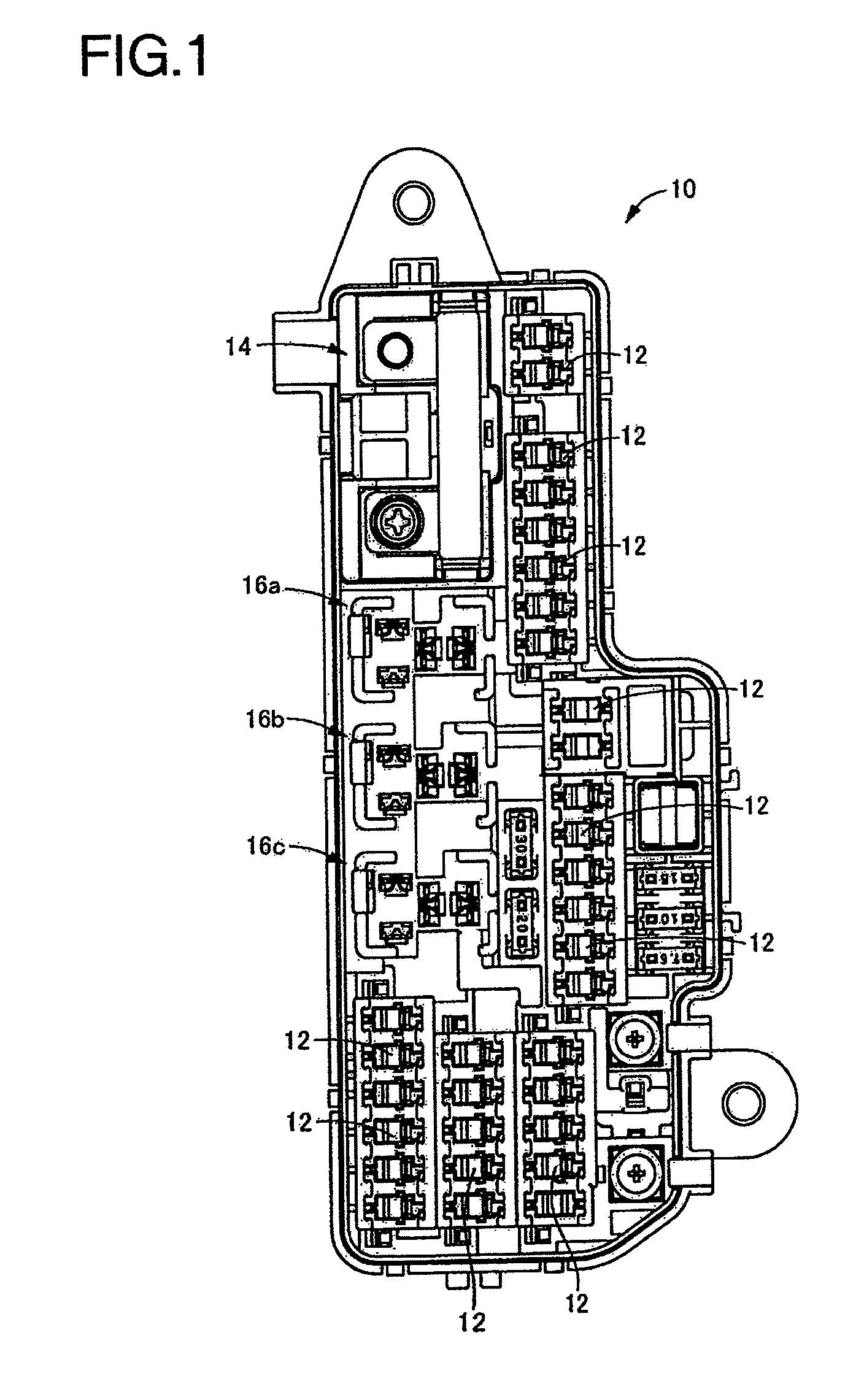
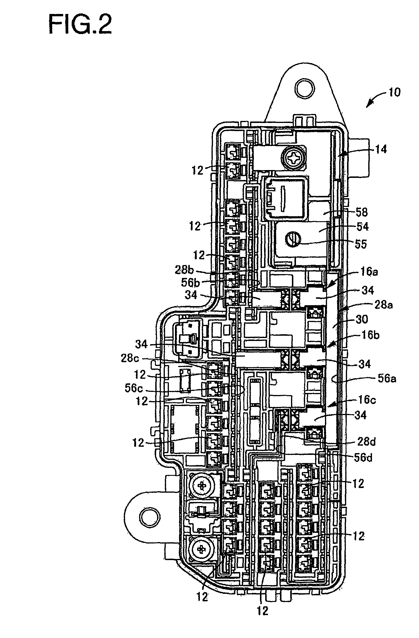
[0034]A front surface of an electric junction box 10 is first shown in FIG. 1, as an embodiment of the present invention. A rear surface of the electric junction box 10 is then shown in FIG. 2. The electric junction box 10 accordi...


PUM


Abstract

A vertical bus bar is provided to a side of a relay mount portion. A flat bus bar portion is integrally provided extending from an end edge portion of the vertical bus bar to an opening of a terminal connection hole of the relay mount portion. A plurality of connection terminals, including a connection terminal for a switch, are integrally provided to the flat bus bar portion.

Description

CROSS-REFERENCE TO RELATED APPLICATIONS[0001]The present application claims priority under 35 U.S.C. §119 of Japanese Application No. 2009-254453, filed on Nov. 5, 2009, which is herein expressly incorporated by reference in its entirety.BACKGROUND OF THE INVENTION[0002]1. Field of the Invention[0003]The present invention relates to an electric junction box mounted to a vehicle and the like, particularly relates to an electric junction box provided with a relay mount portion and a bus bar for conduction with the relay mount portion.[0004]2. Description of Related Art[0005]Electric junction boxes, such as relay boxes, fuse boxes, and the like, are conventionally used in vehicles and the like, in order to improve efficiency of electric wiring and maintenance performance. Electrical components, such as relays, fuses, and the like, and conducting members, such as bus bars and the like, are appropriately mounted to an electric junction box. Electric power from a battery and the like is t...

Claims


Application Information

Patent Timeline
Patent Type & Authority Patents(United States)
IPC IPC(8): H05K7/02
CPCH05K7/026
Inventor MATSUI, TOSHIYUKI
Owner SUMITOMO WIRING SYST LTD
Why Eureka
Try Eureka