
Method and apparatus for deriving pathloss estimation values

a pathloss and estimation value technology, applied in electrical equipment, transmission monitoring, wireless commuication services, etc., can solve the problems of inaccurate and unrealistic pathloss estimations, expensive and time-consuming undertakings, and the inability to perform such drive tests throughout the entire network, so as to reduce the burden on the operator, alleviate the burden, and eliminate the effect of on

Active Publication Date: 2013-02-12
VIAVI SOLUTIONS UK LTD
View PDF5 Cites 40 Cited by
  • Summary
  • Abstract
  • Description
  • Claims
  • Application Information

AI Technical Summary

Benefits of technology

Enables accurate path loss modeling for individual sectors, improving network planning and optimization by using up-to-date data, reducing the need for frequent drive tests and ensuring accurate representation of the radio environment.

Problems solved by technology

As a result, such known planning and optimization techniques result in inaccurate and unrealistic pathloss estimations, and thus sub-optimal planning and optimization of the network.
Performing such drive tests throughout an entire network is an expensive and time consuming undertaking.

Method used


Image

  • Method and apparatus for deriving pathloss estimation values
  • Method and apparatus for deriving pathloss estimation values
  • Method and apparatus for deriving pathloss estimation values

Examples


Embodiment Construction

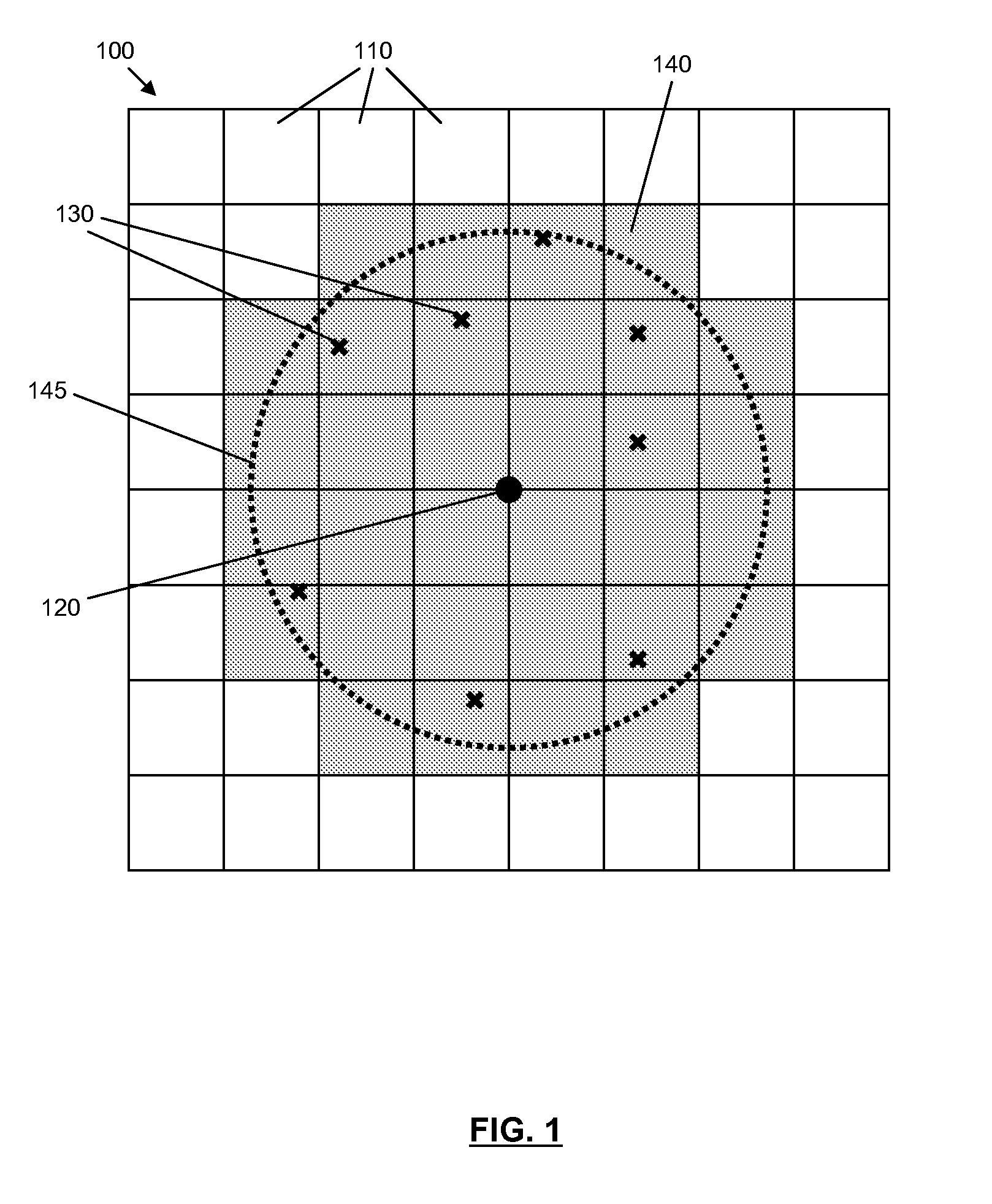
[0034]Referring now to FIG. 1, there is illustrated a simplified example of a representation of a part of a geographical area 100, such as a city, a county, a country, etc, for which pathloss estimations for a cellular communication system are required or desired. The geographical area 100 is divided into area bins 110, which for the illustrated example are tessellated in a regular manner, and in particular for the illustrated example comprise generally square configurations, such that the geographical area 100 is divided up in a checkerboard type pattern. However, it is envisaged that the bins 110 may comprise any suitable dimensions or form. For example, in some embodiments each bin may be between fifty to two hundred meters to a side. Thus, for a typical bin size of, say, 100 meters by 100 meters, each bin 110 comprises an area of 0.01 square kilometers.

[0035]Typically, wireless communication units, or User Equipment (UE) as they are often referred to in 3G parlance, communicate ...


PUM


Abstract

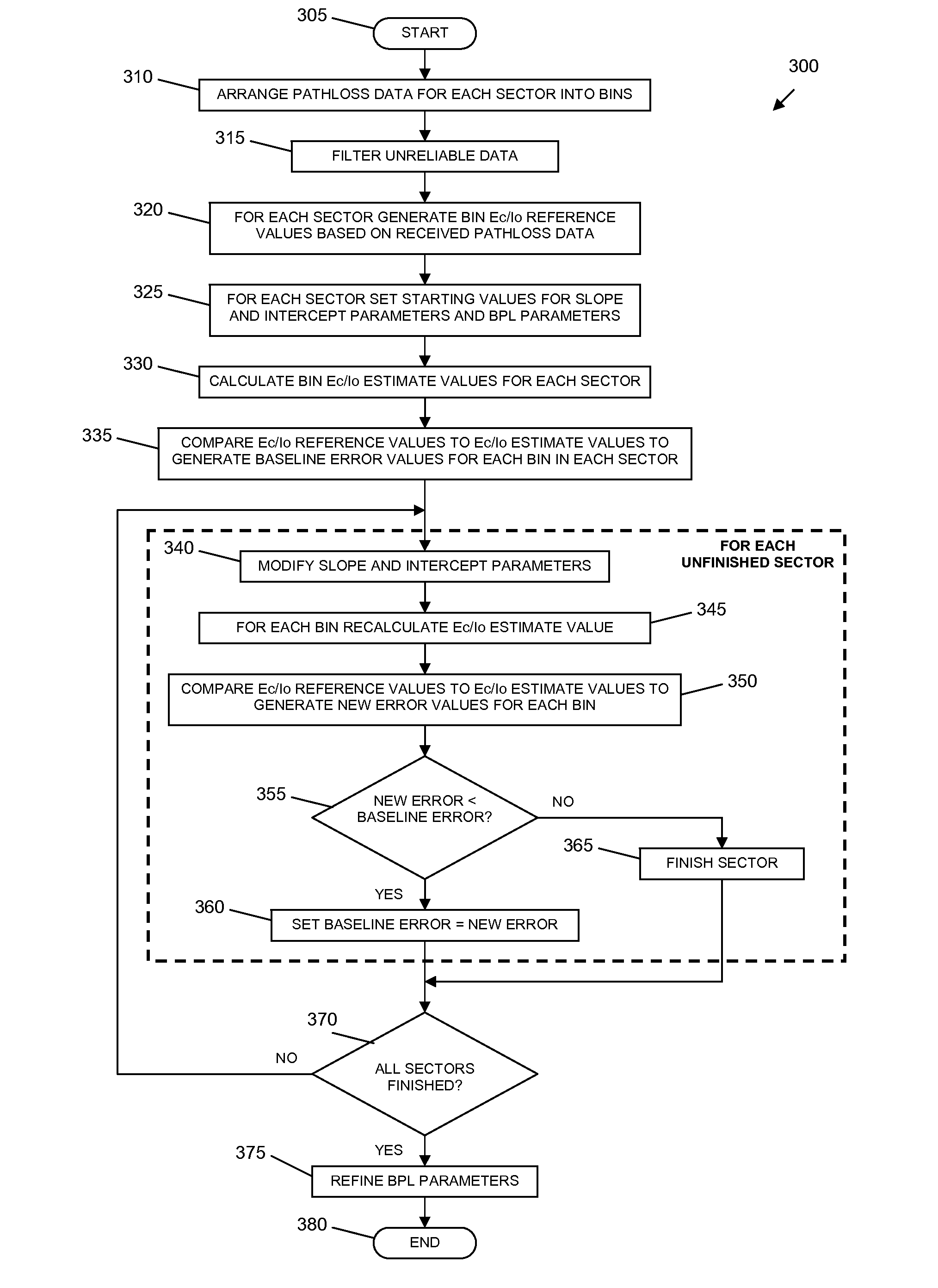
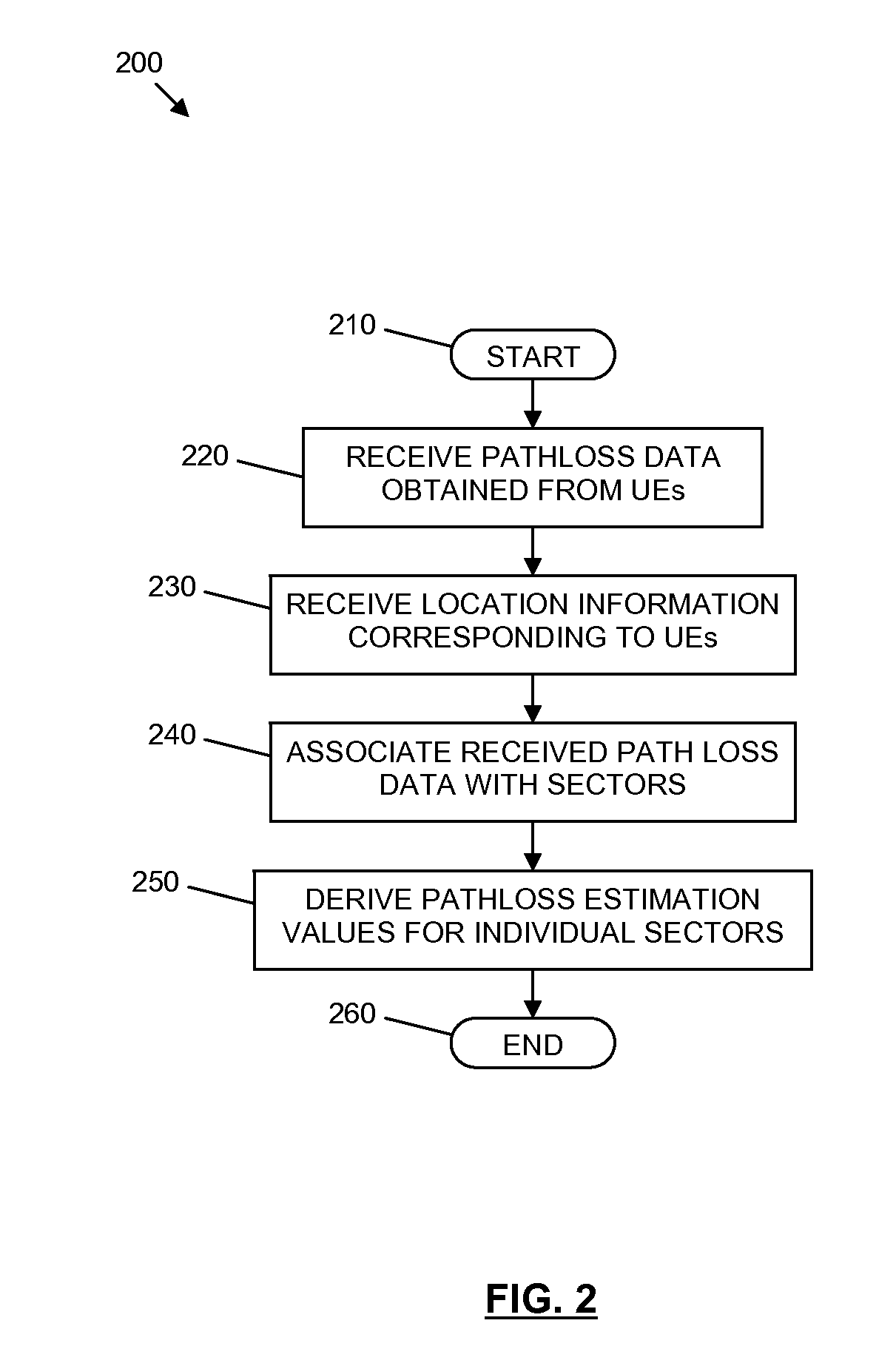
A method for deriving pathloss estimation values within a cellular communication network. The method comprises receiving pathloss data obtained from a plurality of wireless communication units located within the cellular communication network, receiving location information corresponding to the plurality of wireless communications units, associating received pathloss data with individual sectors within a coverage area of the cellular communication network based at least partly on the location information for the respective wireless communications unit, and deriving pathloss estimation values for individual sectors within the cellular communication network based at least partly on the received pathloss data.

Description

CROSS REFERENCE TO RELATED APPLICATION[0001]This application claims priority under 35 U.S.C. §119(e) to U.S. Provisional Patent Application No. 61 / 240,778, filed Sep. 9, 2009, the entire disclosure of which is hereby incorporated herein by reference.FIELD OF THE INVENTION[0002]The field of the invention relates to a method and apparatus for deriving pathloss estimation values, and in particular to a method and apparatus for deriving pathloss estimation values within a cellular communication network.BACKGROUND OF THE INVENTION[0003]Wireless communication systems, such as the 2nd Generation (2G) (otherwise referred to as Global System for Mobile (GSM) communications) and the 3rd Generation (3G) of mobile telephone standards and technology, are well known. An example of such 3G standards and technology is the Universal Mobile Telecommunications System (UMTS), developed by the 3′ Generation Partnership Project (3GPP) (www.3gpp.org).[0004]Typically, wireless communication units, or User ...

Claims


Application Information

Patent Timeline
Patent Type & Authority Patents(United States)
IPC IPC(8): H04W24/00
CPCH04W16/18H04W24/08H04W24/00H04B17/3913H04B17/318
Inventor THIEL, STEFAN ULRICHZADEH-KOOCHAK, MOHSENFLANAGAN, MICHAEL JOSEPH
Owner VIAVI SOLUTIONS UK LTD
Learn More