
Probe card assembly and kit, and methods of making same

a technology of propulsion card and assembly kit, which is applied in the field of propulsion card assembly and kit, and methods of making same, can solve the problems of dies being “good” (full functional), dies being “bad” (non-functional), and certain difficulties inherent in any technique for probing semiconductor dies, so as to achieve convenient control of impedance, easy demountability, and effective shielding

Inactive Publication Date: 2013-02-12
FORMFACTOR INC
View PDF977 Cites 71 Cited by
  • Summary
  • Abstract
  • Description
  • Claims
  • Application Information

AI Technical Summary

Benefits of technology

Enables reliable and efficient testing of semiconductor devices before singulation, accommodating non-planarities and reducing damage to fragile components, with the ability to make connections at fine pitches and allowing for easy adjustment of the space transformer orientation for precise contact.

Problems solved by technology

In practice, however, certain physical defects in the wafer itself and certain defects in the processing of the wafer inevitably lead to some of the dies being “good” (fully-functional) and some of the dies being “bad” (non-functional).
Certain difficulties are inherent in any technique for probing semiconductor dies.
This ring-shape layout makes it difficult, and in some cases impossible, to probe a plurality of unsingulated semiconductor dies (multiple sites) on a wafer, especially when the bond pads of each semiconductor die are arranged in other than two linear arrays along two opposite edges of the semiconductor die.
As a general proposition, the higher the yield strength of a material, the more difficult it will be to work with (e.g., punch, bend, etc.).
Such “hostile” processes are generally not desirable (and often not feasible) in the context of certain relatively “fragile” electronic components such as semiconductor devices.
However, both solder and gold are relatively soft (low yield strength) materials which will not function well as spring elements.
A subtle problem associated with interconnection elements, including spring contacts, is that, often, the terminals of an electronic component are not perfectly coplanar.

Method used


Image

  • Probe card assembly and kit, and methods of making same
  • Probe card assembly and kit, and methods of making same
  • Probe card assembly and kit, and methods of making same

Examples


embodiment 200

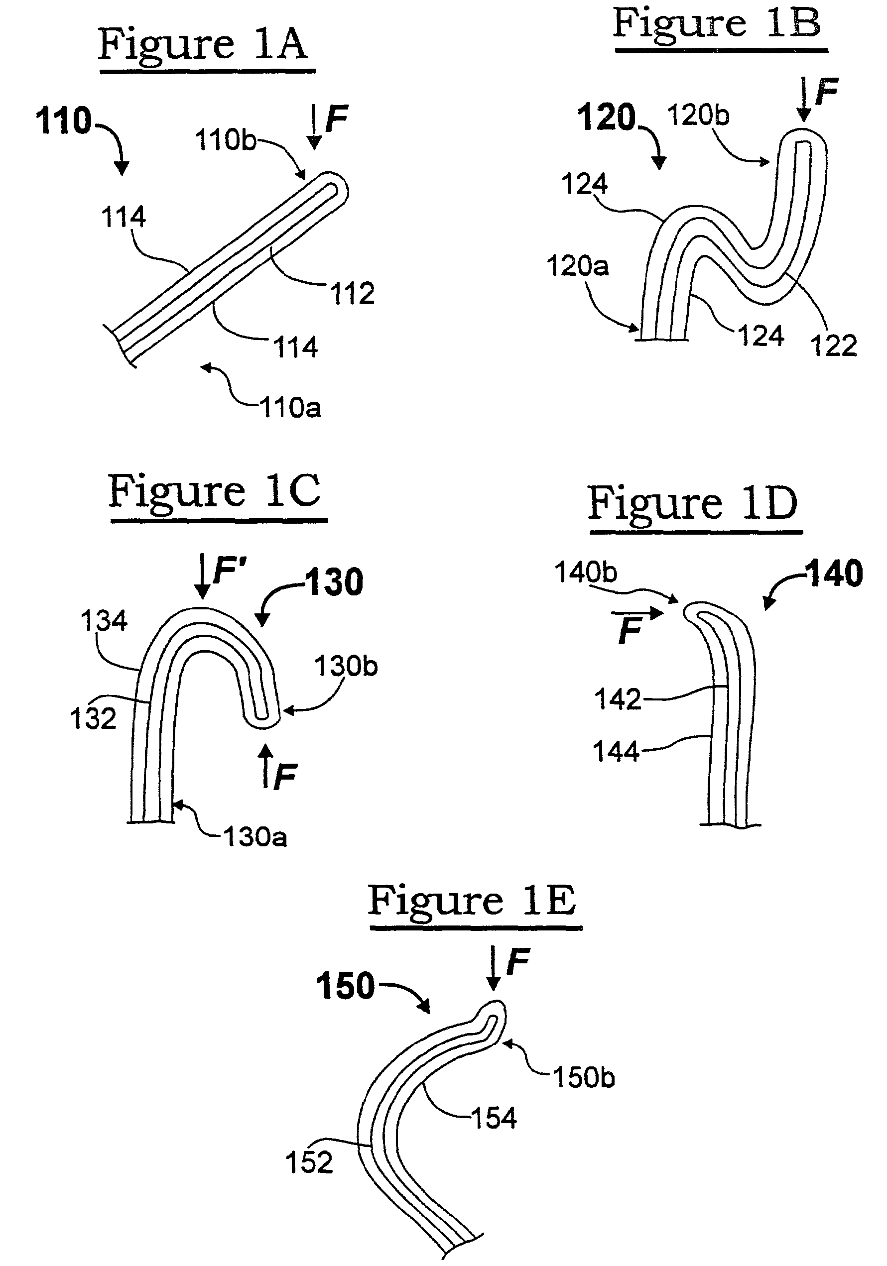
[0114]FIG. 2A illustrates an embodiment 200 of an interconnection element 210 mounted to an electronic component 212 which is provided with a terminal 214. In this example, a soft (e.g., gold) wire core 216 is bonded (attached) at one end 216a to the terminal 214, is configured to extend from the terminal and have a spring shape (compare the shape shown in FIG. 1B), and is severed to have a free end 216b. Bonding, shaping and severing a wire in this manner is accomplished using wirebonding equipment. The bond at the end 216a of the core covers only a relatively small portion of the exposed surface of the terminal 214.

[0115]A shell (overcoat) is disposed over the wire core 216 which, in this example, is shown as being multi-layered, having an inner layer 218 and an outer layer 220, both of which layers may suitably be applied by plating processes. One or more layers of the multi-layer shell is (are) formed of a hard material (such as nickel and its alloys) to impart a desired resilie...

embodiment 250

[0131]FIG. 2C illustrates an embodiment 250 wherein a plurality (six of many shown) of interconnection elements 251 . . . 256 are mounted on a surface of an electronic component 260, such as a probe card insert (a subassembly mounted in a conventional manner to a probe card). Terminals and conductive traces of the probe card insert are omitted from this view, for illustrative clarity. The attached ends 251a . . . 256a of the interconnection elements 251 . . . 256 originate at a first pitch (spacing), such as 0.05-0.10 inches. The interconnection elements 251 . . . 256 are shaped and / or oriented so that their free ends (tips) are at a second, finer pitch, such as 0.005-0.010 inches. An interconnect assembly which makes interconnections from a one pitch to another pitch is typically referred to as a “space transformer”.

[0132]As illustrated, the tips 251b . . . 256b of the interconnection elements are arranged in two parallel rows, such as for making contact to (for testing and / or burn...

embodiment 270

[0147]FIG. 2I illustrates an alternate embodiment 270 for fabricating interconnection elements. In this embodiment, a masking material 272 is applied to the surface of a sacrificial substrate 274, and is patterned to have a plurality (one of many shown) of openings 276, in a manner similar to the technique described hereinabove with respect to FIG. 2D. The openings 276 define areas whereat interconnection elements will be fabricated as free-standing structures. (As used throughout the descriptions set forth herein, an interconnection element is “free-standing” when is has a one end bonded to a terminal of an electronic component or to an area of a sacrificial substrate, and the opposite end of the interconnection element is not bonded to the electronic component or sacrificial substrate.)

[0148]The area within the opening may be textured, in any suitable manner, such as to have one or more depressions, as indicated by the single depression 278 extending into the surface of the sacrif...


PUM

PropertyMeasurementUnit
lengthaaaaaaaaaa
lengthaaaaaaaaaa
diameteraaaaaaaaaa

Abstract

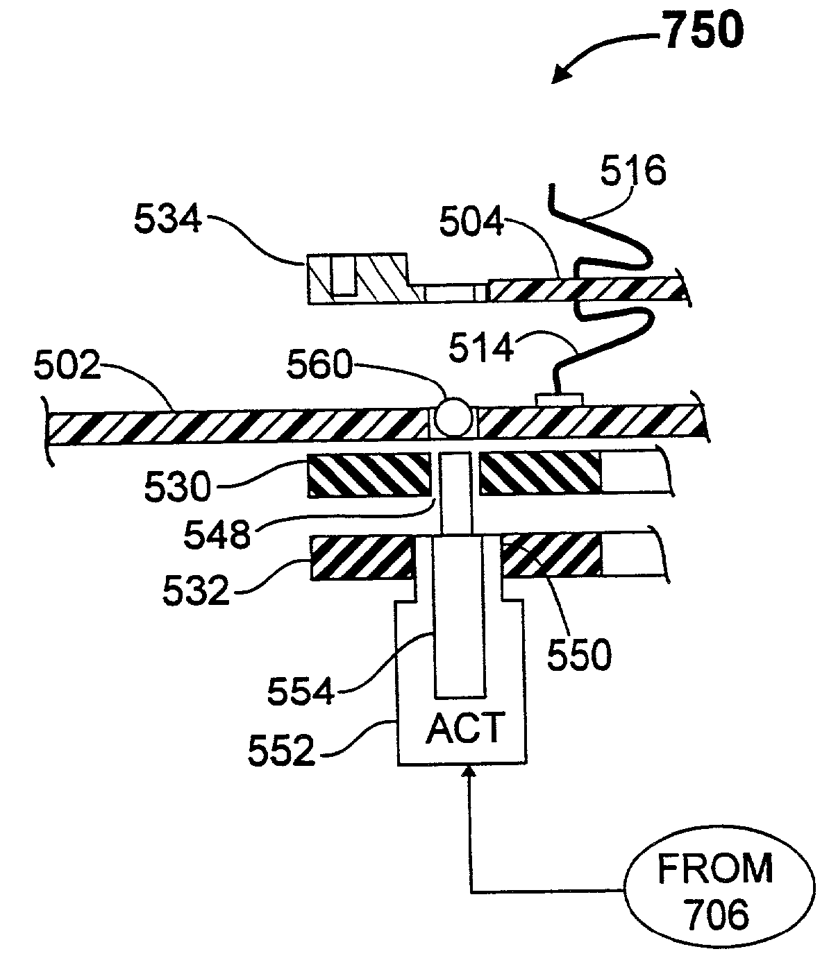
A probe card assembly includes a probe card, a space transformer having resilient contact structures (probe elements) mounted directly to (i.e., without the need for additional connecting wires or the like) and extending from terminals on a surface thereof, and an interposer disposed between the space transformer and the probe card. The space transformer and interposer are “stacked up” so that the orientation of the space transformer, hence the orientation of the tips of the probe elements, can be adjusted without changing the orientation of the probe card. Suitable mechanisms for adjusting the orientation of the space transformer, and for determining what adjustments to make, are disclosed. The interposer has resilient contact structures extending from both the top and bottom surfaces thereof, and ensures that electrical connections are maintained between the space transformer and the probe card throughout the space transformer's range of adjustment, by virtue of the interposer's inherent compliance. Multiple die sites on a semiconductor wafer are readily probed using the disclosed techniques, and the probe elements can be arranged to optimize probing of an entire wafer. Composite interconnection elements having a relatively soft core overcoated by a relatively hard shell, as the resilient contact structures are described.

Description

CROSS-REFERENCE TO RELATED APPLICATIONS[0001]This application is a division of U.S. patent application Ser. No. 10 / 034,528, filed Dec. 27, 2001 (pending), which is a continuation of U.S. patent application Ser. No. 09 / 846,490, filed Apr. 30, 2001 (now U.S. Pat. No. 7,086,149), which is a division of U.S. patent application Ser. No. 09 / 156,957, filed Sep. 18, 1998 (now U.S. Pat. No. 6,246,247), which is a divisional of application Ser. No. 08 / 554,902, filed Nov. 9, 1995 (now U.S. Pat. No. 5,974,662). The foregoing U.S. patent application Ser. Nos. 10 / 034,528, 09 / 846,490, 09 / 156,957, and 08 / 554,902 are incorporated herein by reference in their entirety.[0002]This patent application is a continuation-in-part of commonly-owned, copending U.S. patent application Ser. No. 08 / 452,255 (hereinafter “PARENT CASE”), filed May 26, 1995 (status: pending), which is a continuation-in-part of commonly-owned, copending U.S. patent application Ser. No. 08 / 340,144 filed Nov. 15, 1994 (status: pending)...

Claims


Application Information

Patent Timeline
Patent Type & Authority Patents(United States)
IPC IPC(8): G01R31/00B23K20/00C23C18/16C25D5/08C25D5/22C25D7/12C25D21/02G01R1/067G01R1/073G01R31/28H01L21/00H01L21/48H01L21/56H01L21/60H01L21/603H01L21/66H01L23/48H01L23/485H01L23/49H01L23/498H01L25/065H01L25/16H05K1/14H05K3/20H05K3/30H05K3/32H05K3/34H05K3/36H05K3/40
CPCB23K20/004C25D7/12G01R1/07342G01R1/07378G01R31/2884H01L21/4853H01L21/4889H01L21/563H01L22/20H01L23/49811H01L24/11H01L24/12H01L24/16H01L24/72H01L24/81H01L25/0652H01L25/16H05K3/308H05K3/326H05K3/3426H05K3/4015B23K2201/40C25D5/08C25D5/22C25D21/02G01R31/2886H01L2224/1134H01L2224/13099H01L2224/16145H01L2224/73203H01L2224/81801H01L2224/85201H01L2225/0651H01L2225/06527H01L2225/06555H01L2225/06572H01L2924/01004H01L2924/01005H01L2924/01012H01L2924/01013H01L2924/01015H01L2924/01022H01L2924/01027H01L2924/01029H01L2924/01042H01L2924/01046H01L2924/01047H01L2924/01049H01L2924/01051H01L2924/01074H01L2924/01078H01L2924/01079H01L2924/01082H01L2924/01322H01L2924/014H01L2924/10329H01L2924/14H01L2924/1532H01L2924/19041H01L2924/30107H01L2924/3011H01L2924/3025H05K1/141H05K3/20H05K3/3421H05K3/368H05K2201/068H05K2201/1031H05K2201/10318H05K2201/10757H05K2201/10878H05K2201/10909H05K2201/10946H01L2924/00013H01L2924/01006H01L2924/01019H01L2924/01033H01L2924/01045H01L2924/0105H01L2924/10253Y10T29/49155Y10T29/49222H01L2924/00H01L2924/15787H01L2924/12042H01L2224/45144B23K2101/40Y02P70/50C25D5/605C25D7/123
Inventor ELDRIDGE, BENJAMIN N.GRUBE, GARY W.KHANDROS, IGOR Y.MATHIEU, GAETAN L.
Owner FORMFACTOR INC
Learn More