
Basal thumb joint implant

a thumb joint and implant technology, applied in the field of modules, can solve the problems of unstable thumb joint, disfunctional, painful, reducing rotational stability, one-piece construction or non-modularity of the implant,

Active Publication Date: 2013-02-05
BIOPRO
View PDF18 Cites 7 Cited by
  • Summary
  • Abstract
  • Description
  • Claims
  • Application Information

AI Technical Summary

Benefits of technology

The modular design enhances rotational stability, prevents dislocation, preserves bone stock, and reduces inventory and procedural costs by enabling precise, customizable implant assembly with improved material properties.

Problems solved by technology

Cases of degenerative or post-traumatic arthritis of the trapeziometacarpal joint are known to leave the joint unstable, disfunctional, and painful.
Problems with the foregoing, however, have been discovered to include 1) the straight, non-anatomical countour of the stem, which (a) reduces the rotational stability of the implant, and (b) induces outward mechanical leveraging of the prosthetic head and the proclivity for lateral dislocation of the replaced joint; 2) the demonstrated inferior tribological characteristics of an articulating titanium surface; and 3) the one-piece construction or non-modularity of the implant, which precludes an ability to “mix and match” component parts, consequently requiring a redundant and costly on-the-shelf inventory of implants to assure the availability of an implant which will provide an appropriate head-stem combination that will produce a precise, individualized dimensional fit of both the head and the intramedullary stem parts of the prosthesis.

Method used


Image

  • Basal thumb joint implant
  • Basal thumb joint implant
  • Basal thumb joint implant

Examples


Embodiment Construction

[0029]The invention can be further understood by the present detail, which may be read in view of the drawings. Such is to be taken in an illustrative, and not necessarily limiting, sense.

[0030]In general, the joint implant of the invention includes a head and a stem. It may be one-piece or modular in construction.

[0031]The implant can be made of any suitable material to include biocompatible ceramics, metals, plastics or other suitable material. However, manufacture from a cobalt-containing alloy is beneficially employed since, among other considerations, not the least of which is relative ease of manufacture, a better, more triboligically efficient articular surface can be provided than from the softer titanium, particularly when the implant is of one-piece construction. In modular digital joint implants, the cobalt-containing alloy may be employed for both head and stem components, or, preferably, the cobalt-containing, or other, alloy is employed to make the stem component, and ...


PUM

PropertyMeasurementUnit
angleaaaaaaaaaa
general angleaaaaaaaaaa
sphericityaaaaaaaaaa

Abstract

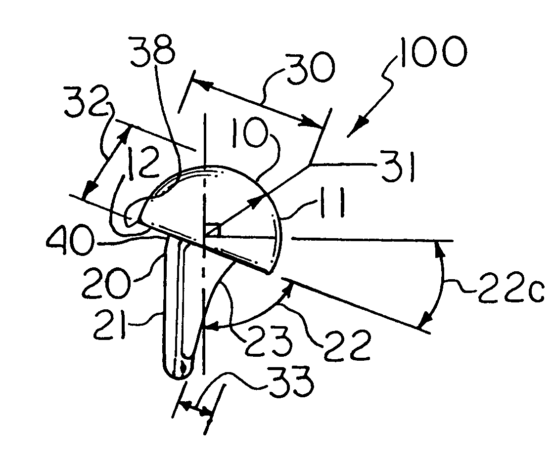
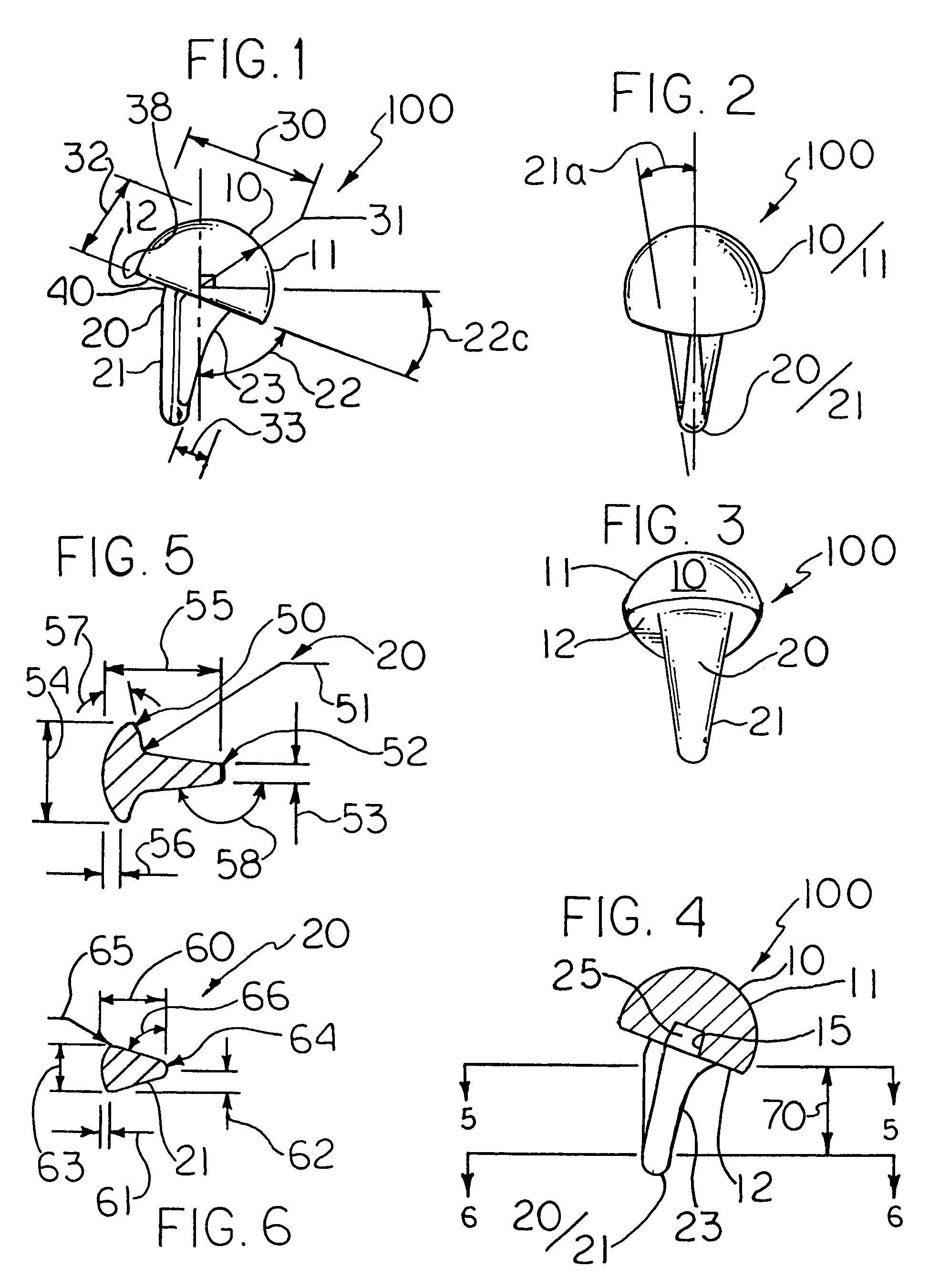
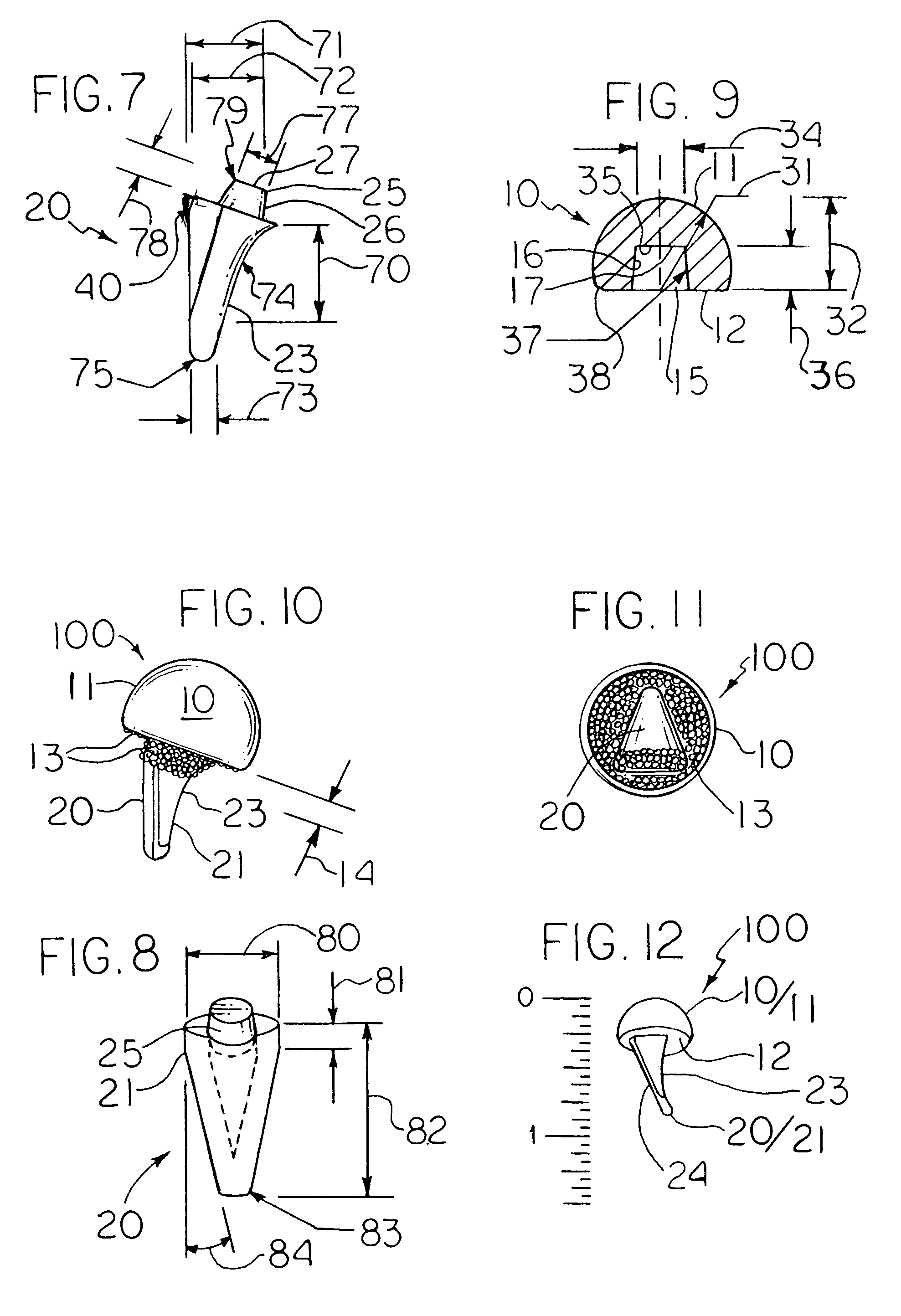
Basal thumb joint implant has a head with a smooth, generally hemispherical, medio-proximally directed, articulating surface, and a generally abrupt, distally directed, truncation thereto; and a stem attached to the head, which arises from the truncation of the head and includes at least one of the following features:A) a general angle of attachment to the head which is acute in relation to the truncation of the head;B) a flanged cross-sectional stem profile;C) an inwardly curved stem;D) an eccentric head attachment site for the stem.The implant may be one-piece or modular in construction. The modular basal thumb joint implant, however, which is not necessarily limited by requiring inclusion of the aforesaid additional features A-D, includes a head with a smooth, generally hemispherical, medio-proximally directed, articulating surface, a generally abrupt, distally directed truncation thereto, and a stem trunion-receiving cup in the truncation; and a stem attachable to the head, which stem has intracarpal spike-like distal end, and a proximally directed trunion, which trunion is insertable into the stem trunion-receiving cup of the head. Other digits may be provided with analogous implants, particularly with respect to those digital implants amenable to modularity.

Description

BACKGROUND TO THE INVENTION[0001]I. Field and Purview of the Invention:[0002]The present invention concerns in particular a one-piece or a modular basal thumb joint implant for the trapeziometacarpal joint, and can also include an extension of the concept of modularity to other digital joints. The implant generally includes head and stem portions, and it has one or more of the following: a generally acute head-stem attachment orientation; a flanged cross-sectional stem profile; an inwardly curved stem; and an eccentric head attachment site for the stem.[0003]II. Prior Art, and Discovered Problems:[0004]Cases of degenerative or post-traumatic arthritis of the trapeziometacarpal joint are known to leave the joint unstable, disfunctional, and painful. In addressing this problem, the Swanson Basal Thumb Joint was developed for use as an adjunct to resection arthroplasty of the joint. The Swanson implant has a generally simple, linearly straight, non-curved stem, which is squarelike in c...

Claims


Application Information

Patent Timeline
Patent Type & Authority Patents(United States)
IPC IPC(8): A61F2/42
CPCA61F2/4241A61F2002/30011A61F2002/30029A61F2002/30112A61F2002/30172A61F2002/30299A61F2002/30332A61F2002/3092A61F2002/4258A61F2310/00413A61F2002/30028
Inventor TOWNLEY, CHARLES O.
Owner BIOPRO
Learn More