Apparatus having a movable body
a technology of movable bodies and apparatuses, applied in the direction of acceleration measurement using interia forces, turn-sensitive devices, instruments, etc., can solve the problems of poor detection accuracy, inability to independently detect the respective displacement in the x-axis direction and the z-axis direction, and conventional technologies that do not address the rotation of the first mass, etc., to achieve excellent resistance to oscillatory disturbances and excellent resistance to shocks
- Summary
- Abstract
- Description
- Claims
- Application Information
AI Technical Summary
Benefits of technology
Problems solved by technology
Method used
Image
Examples
first embodiment
[0050]A. Configuration of an Angular Rate Sensor According to a
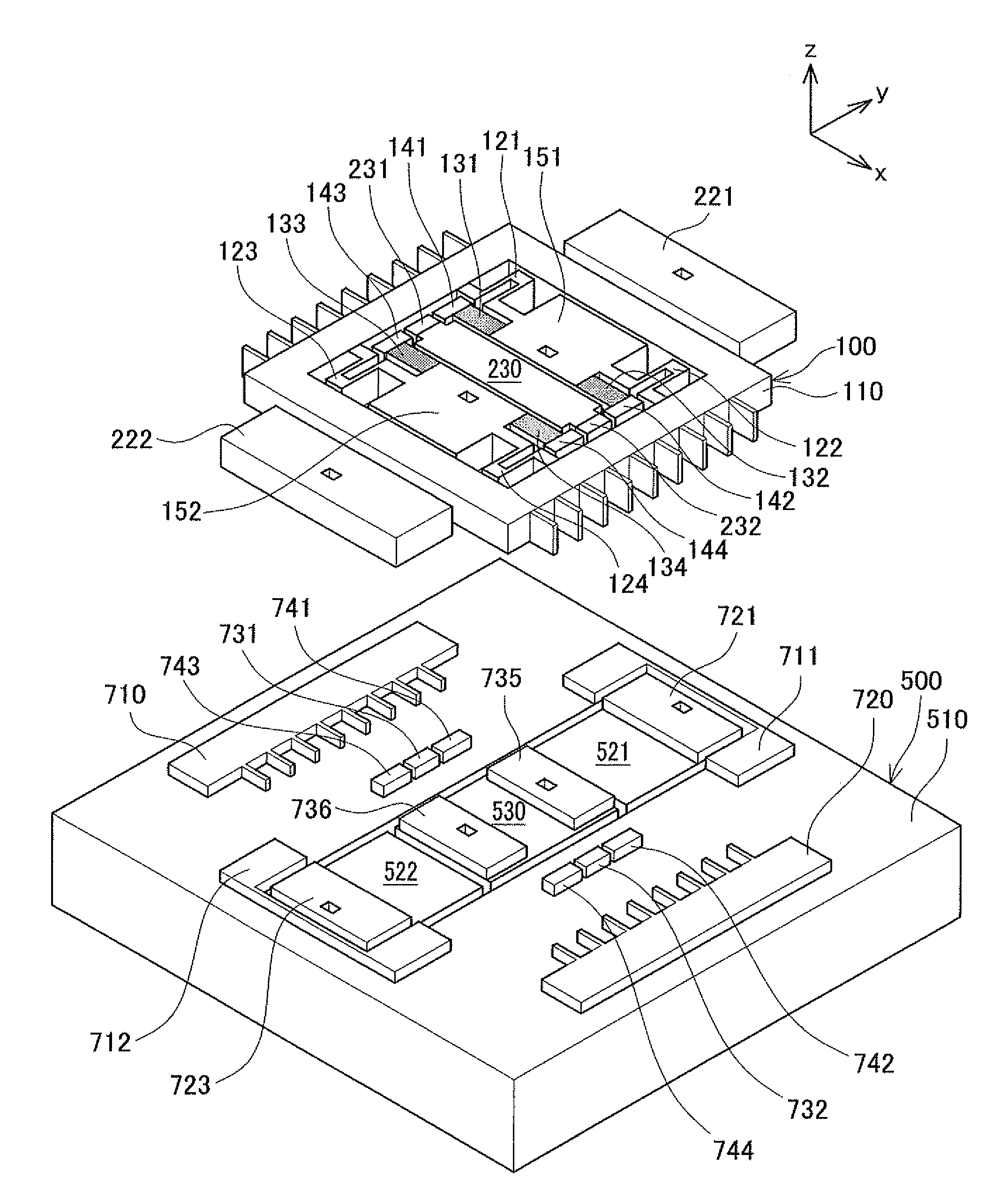
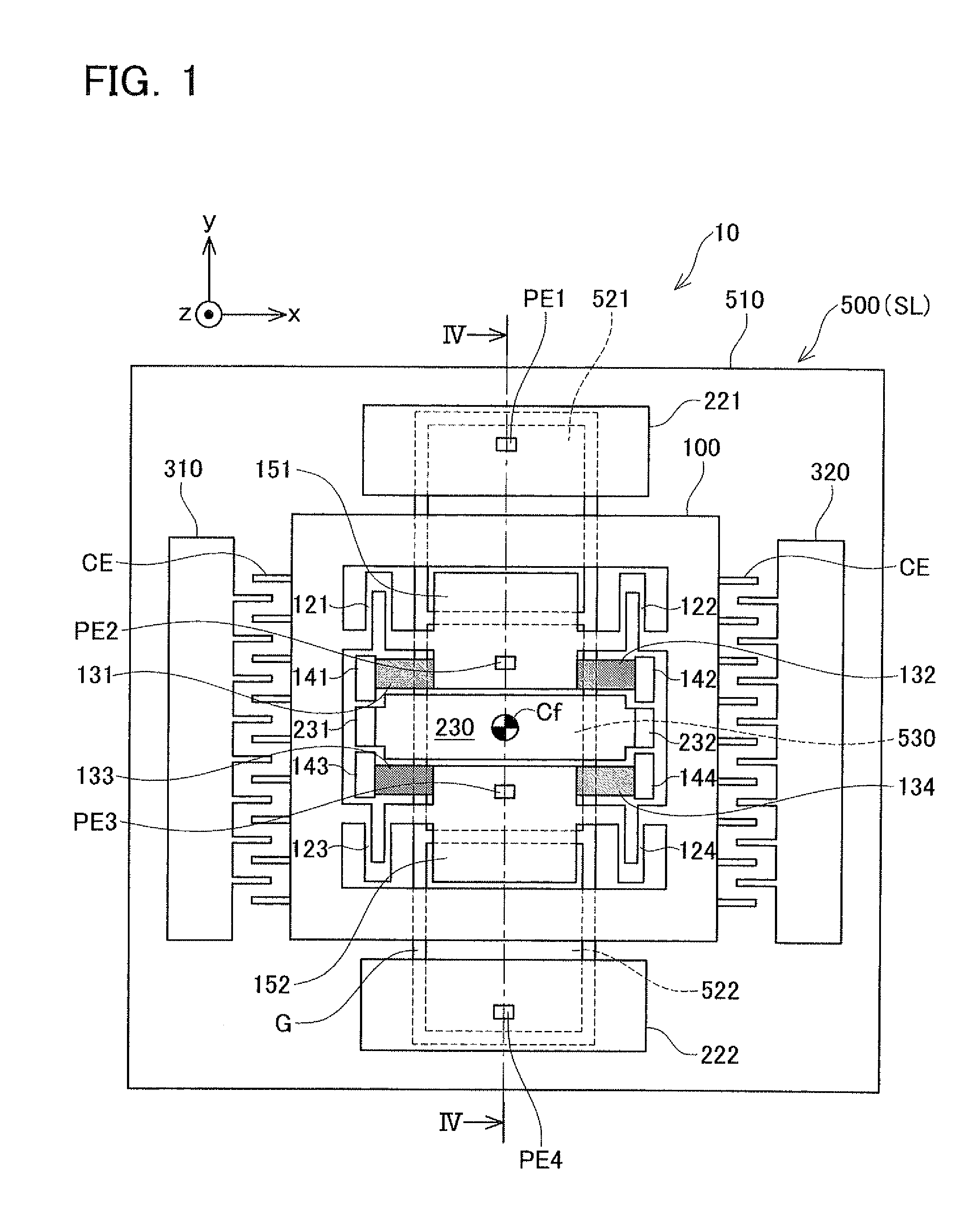
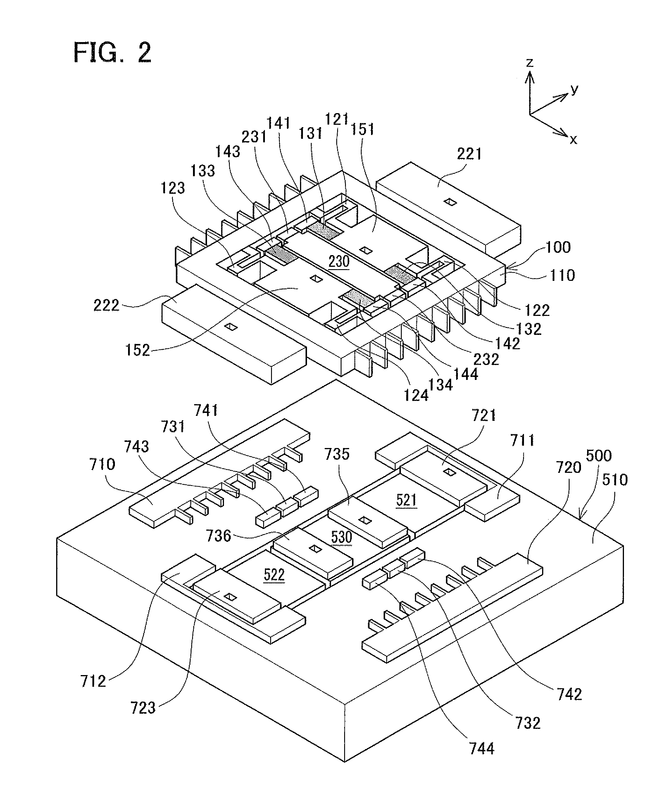
[0051]The configuration of the angular rate sensor according to the first embodiment will be described with reference to FIGS. 1-7. An angular rate sensor 10 comprises a movable body 100, three fixed electrodes 221, 222, 230, a pair of excitation electrodes 310, 320, and a support substrate 500 that supports the foregoing via a buried oxide film BL. The angular rate sensor 10 is composed with an SOI (Silicon on Insulator) substrate. The SOI substrate has a stacked structure comprising a conductive active layer WL (an example of the third layer) and the support substrate SL (an example of the first layer) with the buried oxide film BL (an example of the second layer) interposed therebetween. The movable body 100, the three fixed electrodes 221, 222, 230 and the pair of excitation electrodes 310, 320 are formed on the active layer WL, as illustrated in FIGS. 1 and 2. The active layer WL and the support substrate SL are ele...
second embodiment
[0074]B. Configuration of an Angular Rate Sensor According to the
[0075]FIG. 8 illustrates the configuration of an angular rate sensor 10a comprising a movable body 100a according to the second embodiment. FIG. 9 illustrates the configuration of the movable body 100a of the second embodiment. The movable body 100a of the second embodiment differs from the movable body 100 of the first embodiment in that, here, the joining portions 151, 152 of the first embodiment are changed to joining portions 151a, 152a of the second embodiment. Otherwise, the angular rate sensor 10a of the second embodiment shares the same features of the angular rate sensor 10 of the first embodiment.
[0076]The joining portions 151a, 152a of the second embodiment differ from the joining portions 151, 152 of the first embodiment (FIG. 4) in that the connection positions of the inner fixed portions 141 to 144 and the x-axis springs 121 to 124 are exchanged. Specifically, the positions of the inner fixed portion 141 ...
third embodiment
[0078]C. Configuration of an Angular Rate Sensor According to the Present Invention:
[0079]The third embodiment will be describes with reference to FIGS. 10-12. An angular rate sensor 10b of the third embodiment differs from the angular rate sensor 10 of the first embodiment in that the movable body 100 and the support substrate 500 of the first embodiment are changed to a movable body 100b and a support substrate 500b, and in that two penetrating electrodes PE2, PE3 of the first embodiment have been omitted.
[0080]The movable body 100b of the third embodiment differs from the movable body 100 of the first embodiment in that the movable body 100b is fixed to a support outer substrate 510b in a swastika layout. The specific dissimilar features are as follows (cf. FIG. 11).
(1) The pair of joining portions 151, 152 is changed to one joining portion 151b (an example of the first movable portion).
(2) The inner fixed portions 141 to 142 are changed to inner fixed portions 141b to 142b.
(3) ...
PUM
 Abstract
Description
Claims
Application Information
 - R&D
- Intellectual Property
- Life Sciences
- Materials
- Tech Scout
- Unparalleled Data Quality
- Higher Quality Content
- 60% Fewer Hallucinations
Browse by: Latest US Patents, China's latest patents, Technical Efficacy Thesaurus, Application Domain, Technology Topic, Popular Technical Reports.
© 2025 PatSnap. All rights reserved.Legal|Privacy policy|Modern Slavery Act Transparency Statement|Sitemap|About US| Contact US: help@patsnap.com


