Pipe joining tool

a pipe and tool technology, applied in the field of pipe joining tools, can solve the problems of substantial labor costs, substantial labor costs in terms of labor hours, and substantial risks of disrupting the trench, and achieve the effects of no damage to the pipes, no clamping flexion, and no friction applied by the clamping to the pipes

Inactive Publication Date: 2013-02-05
BASILIERE JAMES
View PDF14 Cites 3 Cited by
  • Summary
  • Abstract
  • Description
  • Claims
  • Application Information

AI Technical Summary

Benefits of technology

[0014]In an alternative embodiment the first and second pipe securing clamps are pivotally secured respectively within the first and second downward facing C-shaped frames for limited rotation of the clamps about first and second pivot axes passing between opposed sides of the C-shaped frames supporting the clamps. The first and second pipe securing clamps include pivot stops configured to extend from the clamps into pivot slots defined within the downward facing C-shaped frames to limit pivoting of the clamps. By permitting the pipe securing clamps to pivot about their pivot axes as the pipe securing heads move toward or away from each other, the first and second clamps remain normal to, or perpendicular to a flow axis through the pipes, so that friction applied by the clamps to the pipes does not decrease, and so that the clamps can do no damage to the pipes.
[0015]Additionally, the pipe joining tool may include the pivot stops and the pivot slots in each of the first and second pipe securing heads being cooperatively configured to permit pivoting of the pipe securing clamps about their respective pivot axes about twenty degrees above or below a plane defined as extending from their pivot axes and parallel to planes defined by the respective central openings. In a further embodiment, the pipe joining tool may also include a pivot plate pivotally secured to the first or second neck and dimensioned to cover an area at least as big as the central opening of the first or second pipe securing heads. In use of the pivot plate, if the first pipe is a structure having an open end near the end to be joined to the second pipe, such as the first pipe being a short coupling, or a T-joint, etc., then the pivot plate may be pivoted from a storage position adjacent the neck to a blocking position covering the central opening of the first pipe securing head. Blocking the opening prevents any soil particles or related debris from entering the first pipe as the pipe joining tool is used to move the pipes to thereby join the first pipe to the second pipe. When the pipes pulled by the tool to be adjacent each other, the pivot plate is pivoted back from a blocking position to a storage position so that the smaller diameter pipe end may be drawn into the larger diameter pipe end to join the pipes with no or very limited contamination by soil particles.

Problems solved by technology

However, joining underground pipes together necessarily requires substantial labor, risks and costs.
Not only does this require significant labor cost in terms of labor hours, but it also gives rise to substantial risks of disrupting the trench by cave-ins of trench walls.
Additionally, soil particles may accumulate adjacent open pipe ends as they are forced together so that some such soil particles may enter and remain in the open pipes, causing further costs in purging contaminants from the joined pipe sections.
Where such trenches are below a frost-line of for example four feet, substantial costs are incurred to make an entire trench sufficiently wide to facilitate manual labor within the trench that is necessary to join sections of pipe together.
Such known pipe joining tools for working in confined work spaces such as deep trenches, however, still require complicated mechanisms that are susceptible to breaking, that are costly, and that also require manual application of pipe engaging chains, cables, engaging clamps, securing tools, etc.
This gives rise to further risks of cave-ins of trenches, contamination of open pipe ends, and breakage of the tools.

Method used


Image

  • Pipe joining tool
  • Pipe joining tool
  • Pipe joining tool

Examples


Embodiment Construction

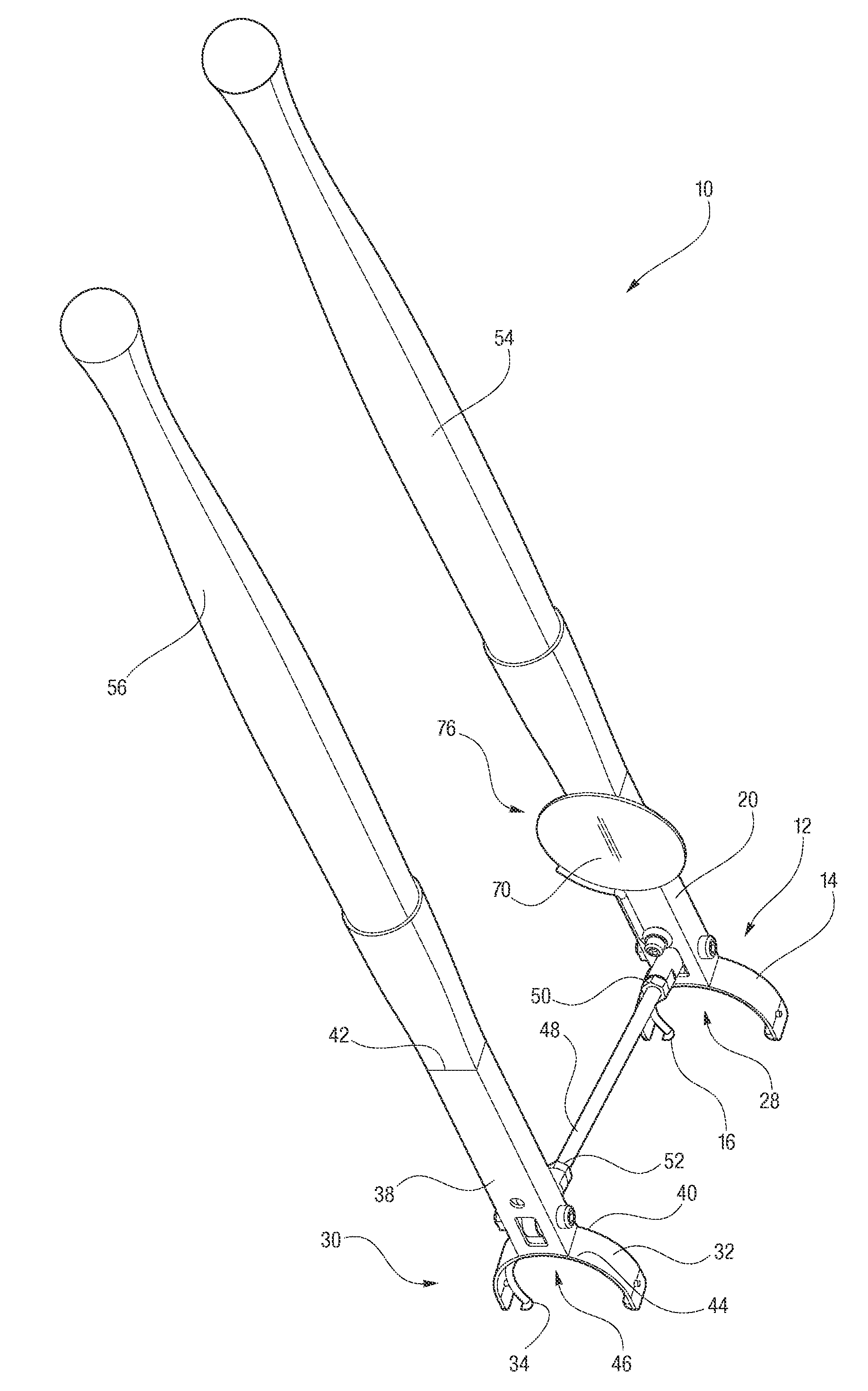
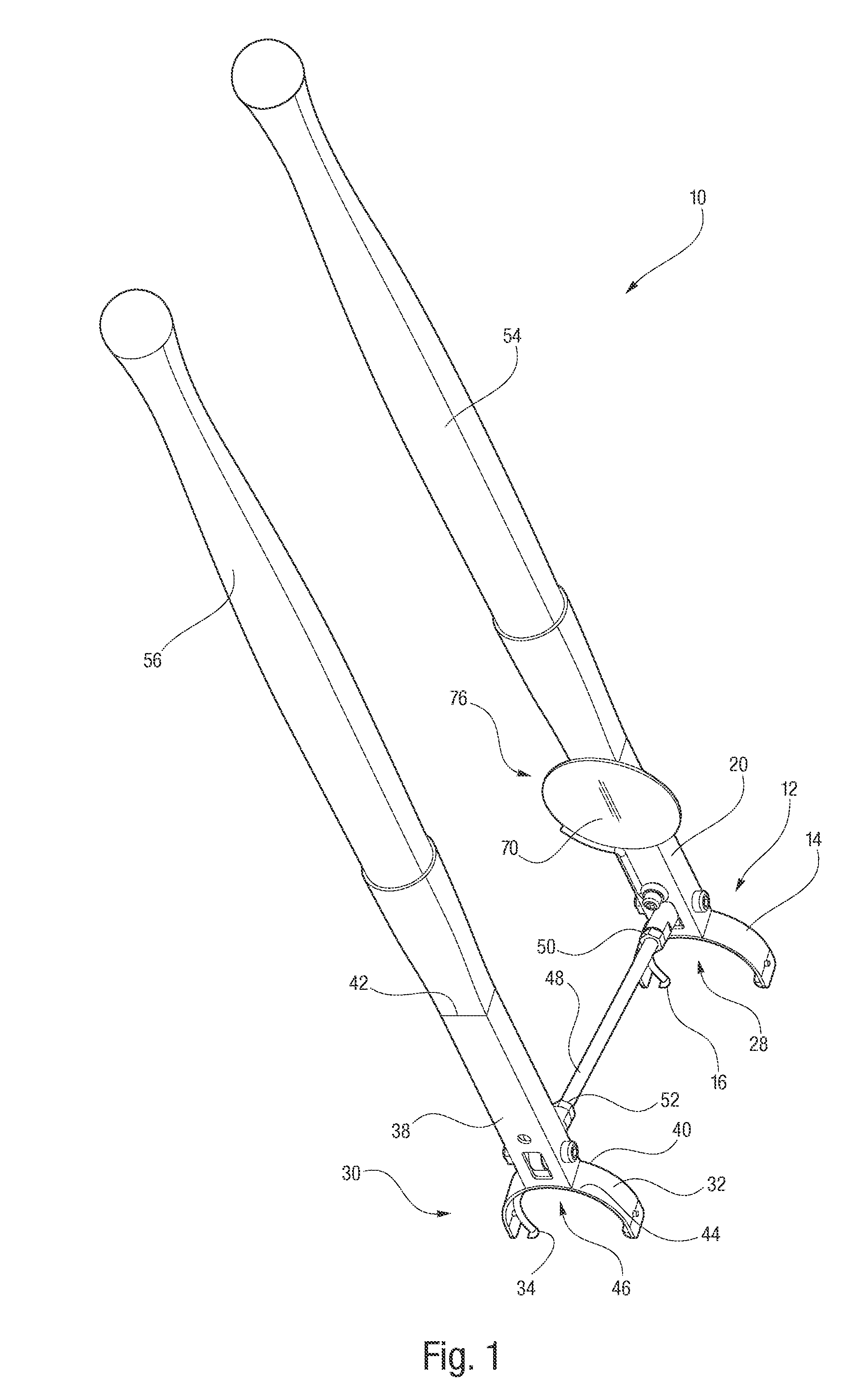
[0040]Referring to the drawings in detail a perspective view of a pipe joining tool of the present disclosure is shown in FIG. 1 and is generally designated by the reference numeral 10. The pipe joining tool 10 includes a first pipe securing head 12 having a first downward facing C-shaped frame 14 and a first pipe securing clamp 16 (seen best in FIG. 2) secured within the first downward facing C-shaped frame 14 for selectively and detachably securing the first pipe securing head 12 to a first pipe 18, shown in FIG. 4. A first neck 20 of the first pipe securing head 12 has a bottom end 22 and an opposed top end 24, wherein the bottom end 22 is secured to a central portion 26 of the first downward facing C-shaped frame 14. The top end 24 of the neck 20 extends away from the first frame 14 in a direction away from a first central opening 28 defined by the first downward facing C-shaped frame 14.

[0041]The pipe joining tool 10 also includes a second pipe securing head 30 (shown in FIG. 1...


PUM

PropertyMeasurementUnit
outer circumferenceaaaaaaaaaa
circumferenceaaaaaaaaaa

Abstract

The tool (10) includes first and second pipe securing heads (12, 30), each having downward facing C-shaped frames (14, 16) and pipe securing clamps (16, 36) secured within the frames (14, 16) for selectively and detachably securing the pipe securing heads (12, 20) to sections of pipes (18, 36). A pivot rod (48) is pivotally secured between necks (20, 38) of the heads (12, 30), and handles (54, 56) are secured to the necks (20, 38). The handles (54, 56) and pivot rod (48) are configured so that, after securing the clamps (16, 36) within the frames (14, 16) to adjacent first and second pipes (18, 36), movement of the handles (54, 56) toward or away from each other causes the pipe securing heads (12, 30) to move the pipes (18, 36) to be joined together or separated.

Description

CROSS REFERENCE TO RELATED APPLICATION[0001]This Application claims the benefit of U.S. Provisional Patent Application Ser. No. 61 / 274,817 that was filed on Aug. 21, 2009, entitled “Pipe Joining Tool”.TECHNICAL FIELD[0002]This disclosure relates to apparatus and tools utilized in securing cylindrical shaped, tubular structures together, and particularly relates to a tool for joining pipes together.BACKGROUND ART[0003]It is well known that pipe's, and pipe-shaped objects are routinely used for transporting fluids both above and underground. For example, oil refineries use a vast array of above ground pipes, while underground pipes transport municipal water supplies, irrigation water, drainage water, etc. Above ground pipes may be readily joined together by well known methods including threaded mechanical connections, welding, bonding etc. However, joining underground pipes together necessarily requires substantial labor, risks and costs. (For purposes herein, the words “pipe” and “pi...

Claims


Application Information

Patent Timeline
Patent Type & Authority Patents(United States)
IPC IPC(8): B23P11/00B25B27/14
CPCB25B27/16Y10T29/53943Y10T29/53778
Inventor BASILIERE, JAMES
Owner BASILIERE JAMES
Why Eureka
Try Eureka